July 2019
4-33
Xerox® B210 Service Manual
REP 4.13
Repairs - Adjustments
Initial Release
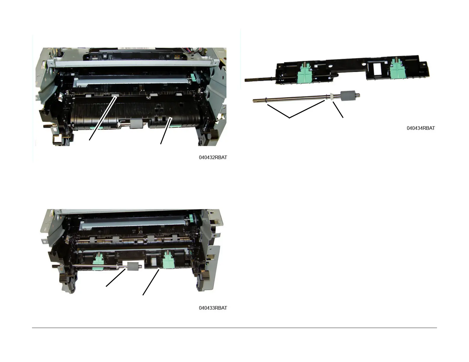
9. Lift the Pinch Rolls and Paper Guide out of the printer, then remove the Feed Assembly
upper half
, Figure 5
.
Figure 5 Registration Pinch Rolls and Paper Guide
10. Remove the Feed Assembly lower half, then remove the Drive Roll from the lower half,
F
igure 6
.
Figure 6 Feed Assembly Lower Half
11. Remove the snap rings and bushing from the Drive Roll Shaft, F
igure 7.
Figure 7 Drive Roll
Replacement
Replacement is the reverse of the removal procedure.
NOTE: Tapered plastic screws and round machine screws are used to hold the cover to the
f
rame. Make sure that the plastic screws go into plastic components and machine screws go
into the metal frame.
1. Install the Drive Roll in the Feed Assembly lower half, ensure the flat on the bu
shing
aligns
with the flat on the assembly
2. Install the Feed Assembly upper half, install the two Feed Assembly bottom screws, t
hen
rout
e the wires through the frame. Refer to, Figure 6 in the removal procedure.
Pinch Rolls &
Paper Guide
Upper Half
 Loading...