July 2019
4-38
Xerox® B210 Service Manual
REP 4.15
Initial Release
Repairs - Adjustments
4. On the bottom of the Printer, Figure 4:
a. Install the Ground Clip and ground screw.
b. Connect the Drive Motor Connector.
5. Install and tighten the frame screws from the center of the frame out, the front of t
he
pr
inter, then the rear of the printer, Figure 6
:
a. Tighten three Front Paper Path Module screws installed in Step 3b.
b. Tighten two ROS Support screws.
c. Tighten three Rear Middle Frame screws.
d. Tighten two Fuser Module Screws installed in Step 3a.
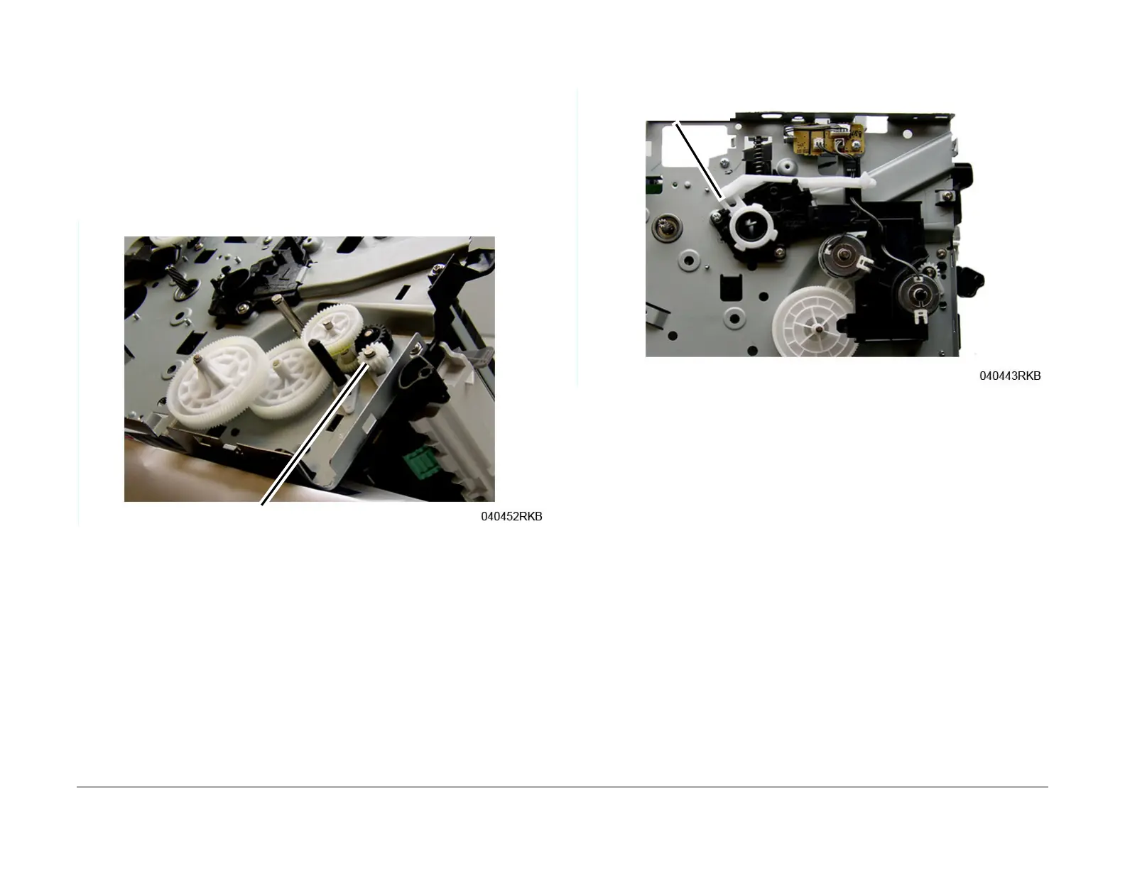
6. Install the Drive Gears, then the snap-ring, F
igure 7.
Figure 7 Feed and Registration Drive Gears
7. Install the remaining components in the reverse of removal.
NOTE: When installing the Front Cover Support Arm make sure it is correctly placed on
t
he stop bracket, Figure 8.
Figure 8 Front Cover Support Arm Placement
 Loading...