July 2019
4-37
Xerox® B210 Service Manual
REP 4.15
Repairs - Adjustments
Initial Release
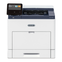
9. Disconnect the Drive Motor connector, then remove the ground screw, Figure 4.
Figure 4 Drive Motor Connector & Ground Clip (Bottom View)
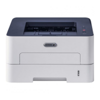
10. Remove three screws in the left frame, F
igure 3.
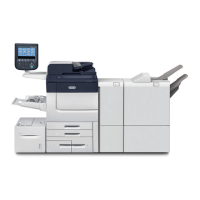
11. Remove four screws, then remove the Drive Motor, Figure 5.
Figure 5 Drive Motor
Replacement
Replacement is the reverse of the removal procedure.
NOTE: Tapered Plastic Screws and Round Machine Screws are used to hold the PWB to the
f
rame. Make sure that the Plastic Screws go into plastic components and Machine Screws go
into the metal frame.
1. Install the new Drive Motor.
NOTE: The Frame is flexible and can be bowed out if the screws are not tightened in t
he
corr
ect order.
Reinstall the Frame as follows so it seats flush against the printer internal modules.
2. Align the Frame on to the int
ernal modules and shafts.
NOTE: Do Not fully tighten the screws in Step 3 until instructed.
3. Install, but do not tighten, the following module screws, F
igure 6:
a. The two Fuser Module screws.
b. The three Middle Frame screws.
Figure 6 Frame Screw Installation
Step 3a
Step 5b
Step 5c
Step 3b
 Loading...