1. Ensure that the Silicon Labs VCP USB-UART drivers are installed Silicon Labs CP210x USB-to-
UART Installaon Guide (UG1033).
2. Download the board user interface Host PC applicaon from the board documentaon web
page.
3. Connect the micro-USB cable to ZCU216 USB-UART connector (J24).
4. Power-cycle the ZCU216.
5. Observe that SYSCTLR LED0 (DS9) blinks and LED1 (DS10) is illuminated.
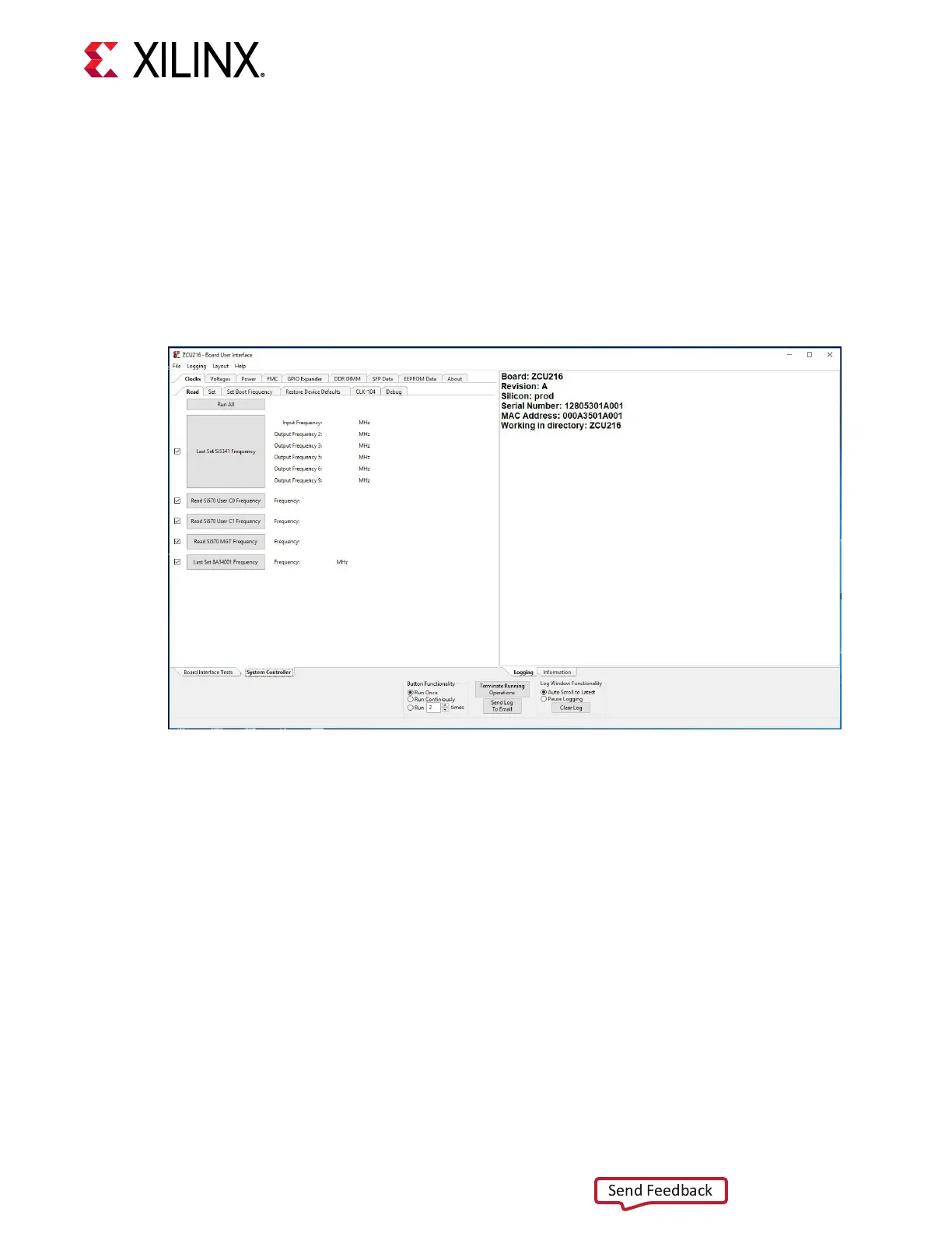
6. Launch the board user interface applicaon.
On rst use of the board user interface, go to the FMC → Set VADJ → Boot-up tab and click USE
FMC EEPROM Voltage. The board user interface buons grey-out during command execuon
and return to their original appearance when ready to accept a new command.
See the ZCU216 System Controller GUI Tutorial (XTP_TBD) and the ZCU216 Soware Install and
Board Setup Tutorial (XTP_TBD) for more informaon on installing and using the System
Controller board user interface ulity.
Switches
[Figure 2, callouts 23 and 24]
The ZCU216 board includes the following power, conguraon, and reset switches:
• SW15 Power On/O slide switch (callout 24)
• SW3 (PS_PROG_B), acve-Low pushbuon (callout 23)
Chapter 3: Board Component Descriptions
UG1390 (v1.1) July 10, 2020 www.xilinx.com
ZCU216 Board User Guide 62

 Loading...


