• SW4 (POR_B), acve-Low pushbuon (callout 23)
• SW5 (SRST_B), acve-Low pushbuon (callout 23)
• SW2 U1 RFSoC PS bank 503 4-pole mode DIP switch (callout 23)
Power On/Off Slide Switch
[Figure 2, callout 24]
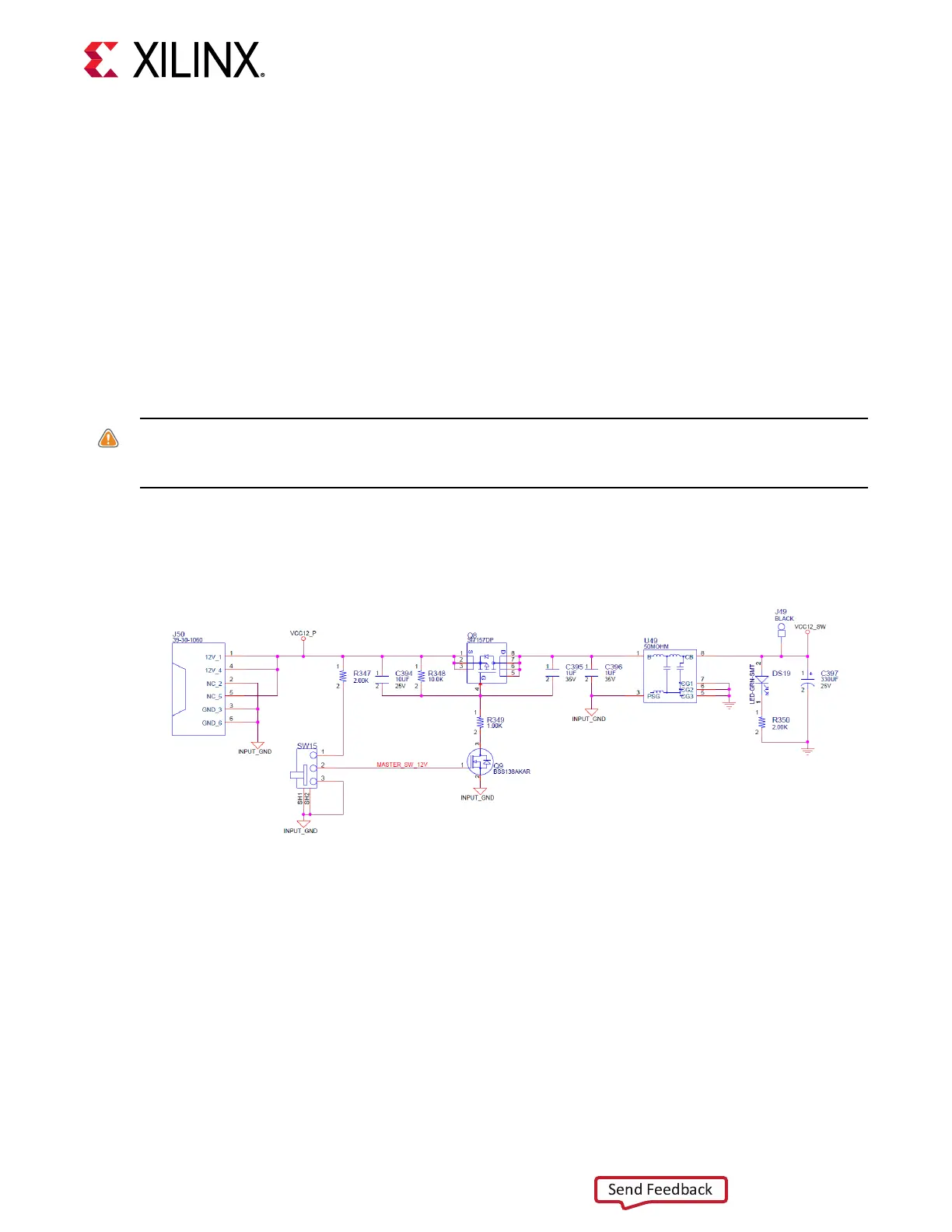
The ZCU216 board power switch is SW15. Sliding the switch actuator from the O to On
posion applies 12V power from J50, a 6-pin mini-t connector. Green LED (DS19) illuminates
when the ZCU216 board power is On. See Board Power System for details on the on-board
power system.
CAUTION! Do NOT plug a PC ATX power supply 6-pin connector into the ZCU216 board power connector
J50. The ATX 6-pin connector has a dierent pinout than J50. Connecng an ATX 6-pin connector into J50
damages the ZCU216 board and voids the board warranty.
The following gure shows the power connector J50, power switch SW2, and LED indicator
DS19.
Figure 20: ZCU216 Power Input
Program_B Pushbutton
[Figure 2, callout 23]
PS_PROG_B pushbuon switch SW3 grounds the ZU49DR RFSoC PS_PROG_B pin P32 when
pressed. This acon clears programmable logic conguraon, which the PS soware can then act
on. See the Zynq UltraScale+ Device Technical Reference Manual (UG1085) for informaon about
the Zynq UltraScale+ RFSoC conguraon.
Chapter 3: Board Component Descriptions
UG1390 (v1.1) July 10, 2020 www.xilinx.com
ZCU216 Board User Guide 63

 Loading...


