ADPRO
®
FastTrace™ 2 Series Hardware Installation Manual
21790_05 63
3. Remove the two cables that connect the LED board on the front to the motherboard. The LEDs will be
powered from the Main I/O card (of the 1
st
set).
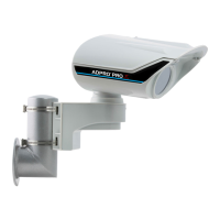
4. Remove the female connectors (A, see figure below) from the Main I/O card before installing.
5. Before inserting the Main I/O card into the motherboard, connect all necessary cables to the card. See
the table below for an overview of cable connections.
Motherboard USB (Intel motherboard: place adapter
#16500660 on the USB connector; MiTAC motherboard: place
adapter #16500665 on the USB connector)
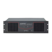
6. Insert the I/O card in the appropriate slot. For more information, see Physical Position on page 60.
7. Connect the cables from the I/O card to the motherboard as indicated.


 To Next Page