Hardware Installation Manual ADPRO
®
FastTrace™ 2 Series
68 21790_05
Although the pictures below show only the connector, it is strongly recommended to connect the
wires with the connectors plugged into the card. Wiring a handheld connector may cause
injuries.
9.11.2 Connecting Inputs/Outputs
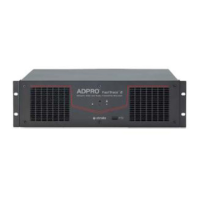
Wiring to Dinkle and Phoenix connectors is identical; except that the position of tabs and holes is swapped.
The picture in the procedure below shows a Phoenix connector.
To connect inputs/outputs, proceed as follows:
1. Push the slotted tab firmly inwards with the screwdriver.
2. Insert the stripped wire (6–7 mm) into the corresponding round hole as deeply as possible.
3. Release the tab and pull the wire to check if it is properly fitted.
Wire gauge:
Solid and stranded: 16–24 AWG
(diam. 1.3–0.5 mm)
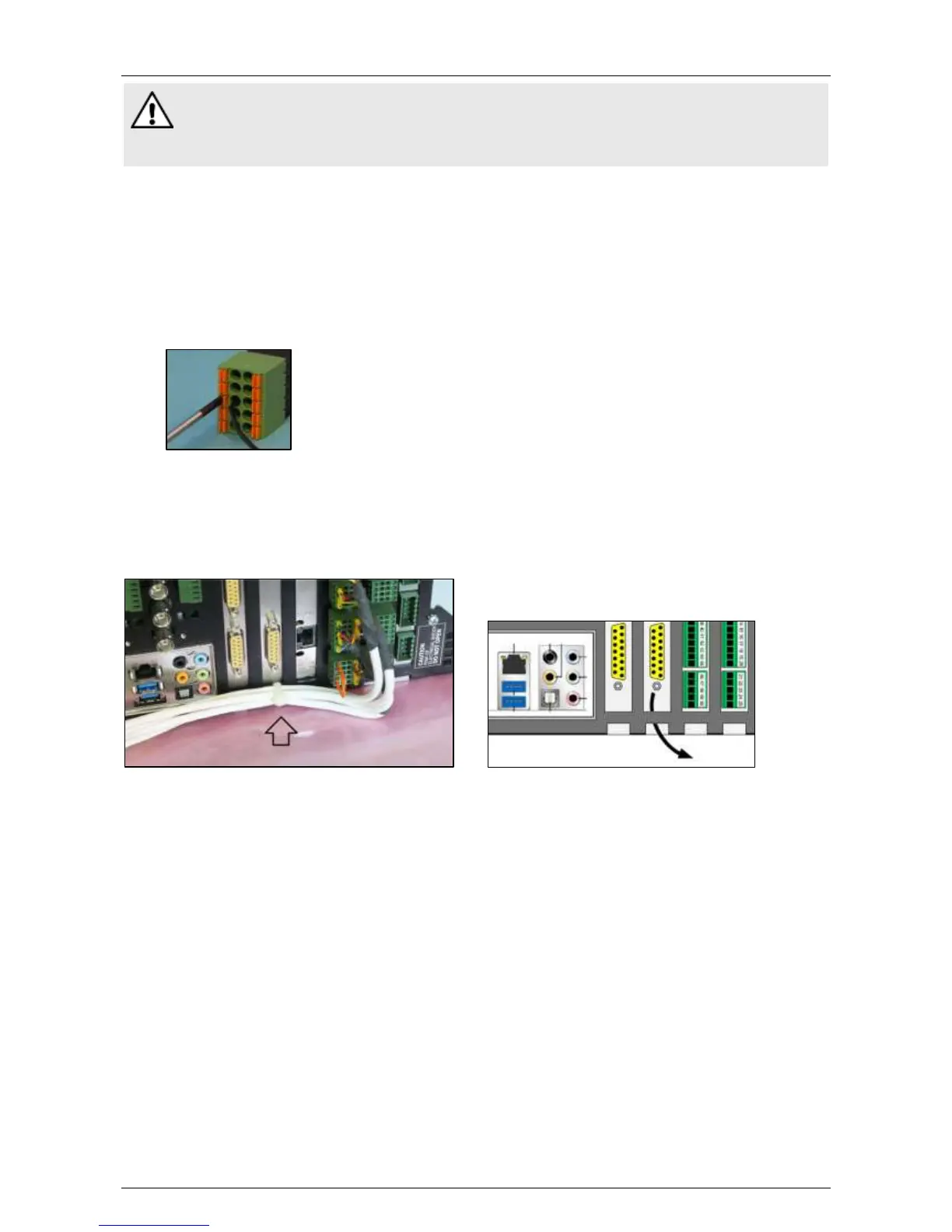
9.11.3 Cable Strain Relief
After connecting all the wires, use a tie-wrap to attach the cables to the chassis. Run the tie-wrap through
one of the extension card openings in the chassis as shown below. The tie-wrap serves as a strain relief and
makes sure that the wiring stays in place when handling the FastTrace 2 unit.
9.12 Configuring the Internal I/O Cards
The FastTrace 2 server automatically detects all connected MIO and EIO cards. To configure the inputs and
outputs, see the XOa Client Software User Manual.
 Loading...