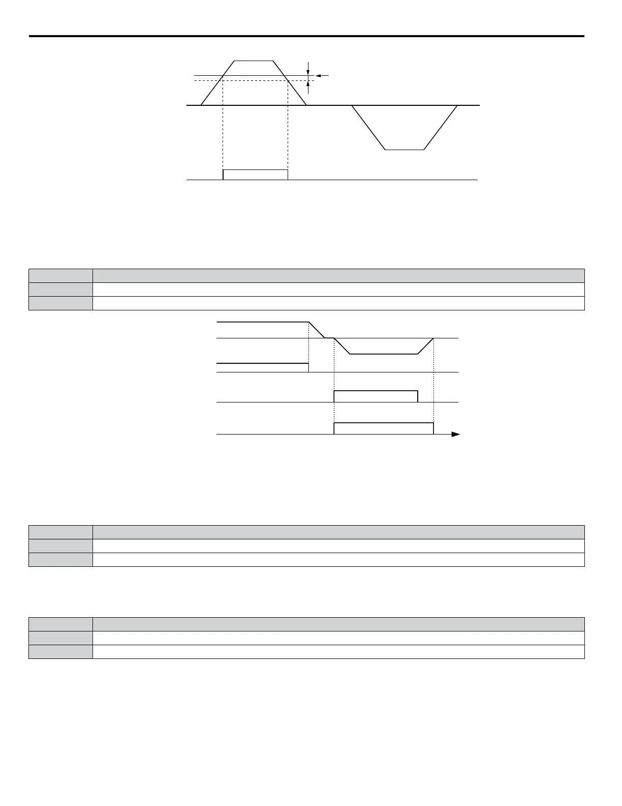
L4-04
Frequency
Detection 4
ON
OFF
L4-03
Output Frequency
Figure 1.71 Frequency Detection 4 Example with Positive L3-04 Value
Refer to L4-03, L4-04: Speed Agreement Detection Level and Detection Width (+/-) on page 145 for more details.
Setting 1A: During Reverse
A digital output set for “During reverse” closes when the drive is running the motor in the reverse direction.
Status Description
Open Motor is being driven in the forward direction or stopped.
Closed Motor is being driven in reverse.
Output frequency
time
FWD Run command
REV Run command
During Reverse
OFF
ON
Figure 1.72 Reverse Direction Output Example Time Chart
Setting 1B: During Baseblock (N.C.)
The output opens to indicate that the drive is in a baseblock state. While Baseblock is executed, output transistors do not switch
and no main circuit voltage is output.
Status Description
Open Baseblock is being executed.
Closed Drive is not in a baseblock state.
Setting 1C: Motor 2 Selection
Indicates which motor is selected when another output terminal is set to switch drive operation between two motors (H1-
oo = 16). Refer to Setting 16: Motor 2 Selection on page 100 for details on switching motors.
Status Description
Open Motor 1 is selected.
Closed Motor 2 is selected.
Setting 1D: During Regeneration
Terminal closes when the motor is driven in the regenerative mode.
Setting 1E: Restart Enabled
An output set for “Restart enabled” closes when the drive attempts to restart after a fault has occurred.
1.7 H: Terminal Functions
112
YASKAWA ELECTRIC SIEP YEAHHP 01B YASKAWA AC Drive – A1000 HHP Programming Manual

 Loading...


