L2-11 (Desired DC Bus Voltage)
DC bus voltage
KEB Digital Input
Main Power Supply
Output Frequency
L2-05 (Uv Detection Level)
0 Hz
0 V
0 V
KEB deceleration is
triggered by DC bus voltage
KEB restart after
L2-02 has passed
Power Loss
Power loss longer than L2-10Power loss shorter than L2-10
L2-10 (Minimum KEB
Operation Time)
L2-11 (Desired DC Bus Voltage)
L2-05 (Uv Detection Level)
0 Hz
0 V
0 V
KEB deceleration is
triggered by DC bus voltage
KEB restart after
L2-02 has passed
Power Loss
L2-10 (Min.
KEB
Operation
Time)
Figure 1.94 KEB Operation Using L2-10 and KEB Input
L2-01 = 5
KEB operation ends when the motor has come to a stop, even if the power returns and the digital input terminal that initiated
KEB Ride-Thru is cleared.
n
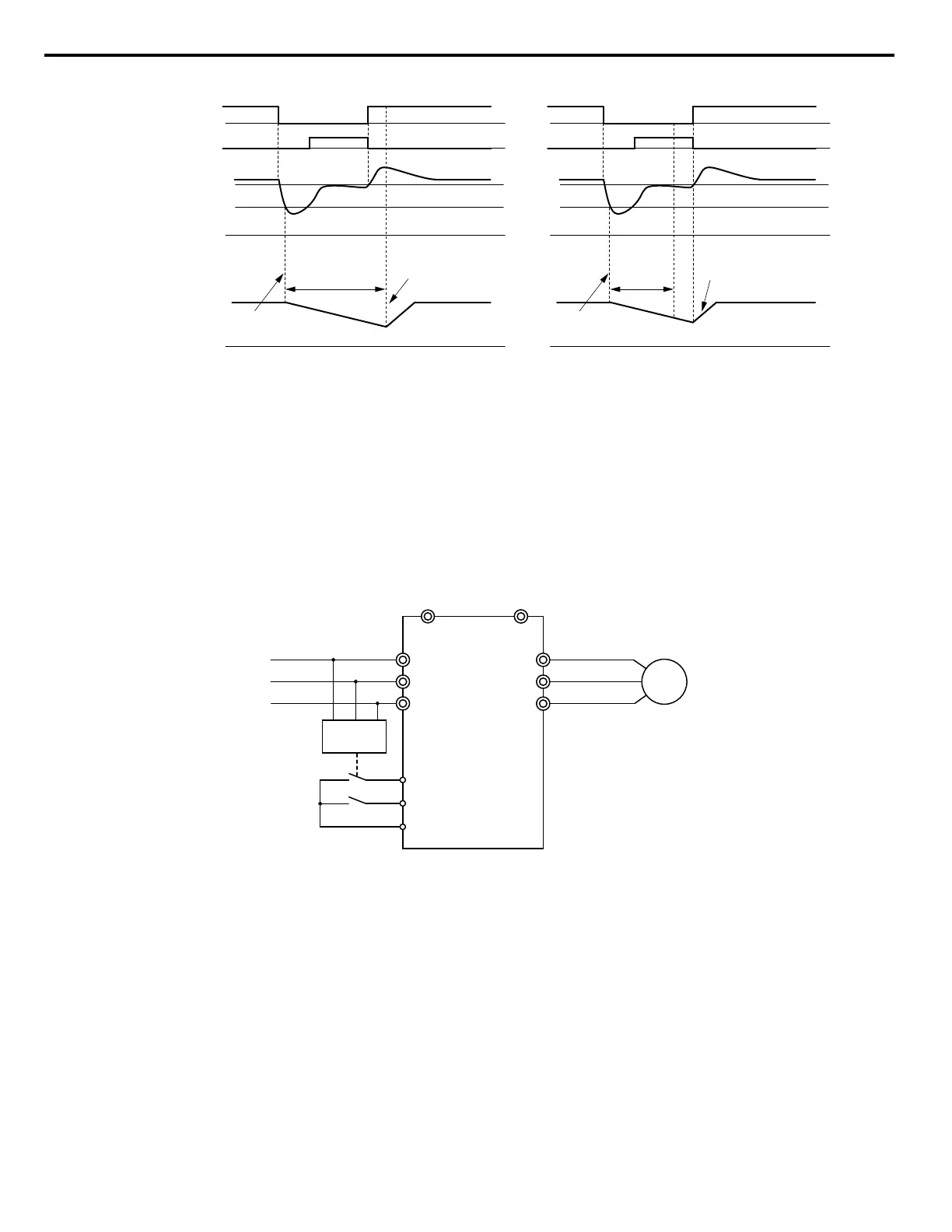
KEB Operation Wiring Example
Figure 1.95 shows a wiring example to trigger the KEB Ride-Thru at power loss using an undervoltage relay. When a power
loss occurs, the undervoltage relay triggers KEB Ride-Thru at terminal S6 (H1-06 = 65, 66). Note that using System KEB
Ride-Thru requires an additional dynamic braking option.
Note: Do not switch off the Run command during momentary power loss. If the Run command is shut off, the drive will not accelerate back to
speed when the power is restored.
M
R/L1
S/L2
T/L3
U/T1
V/T2
W/T3
B1 B2
L1
L2
L3
UV Detection
Relay
S6 - KEB command 1
S1 - Start command
SC
Figure 1.95 KEB Function Wiring Example
n
Parameters for KEB Ride-Thru
Table 1.42 lists parameters needed to set up KEB Ride-Thru.
1.8 L: Protection Functions
138
YASKAWA ELECTRIC SIEP YEAHHP 01B YASKAWA AC Drive – A1000 HHP Programming Manual

 Loading...


