Setting 1: General-purpose Stall Prevention
The drive tries to decelerate within the set deceleration time. The drive pauses deceleration when the DC bus voltage exceeds
the Stall Prevention level and then continues deceleration when the DC bus voltage drops below that level. Stall Prevention
may be triggered repeatedly to avoid an overvoltage fault. The DC bus voltage level for Stall Prevention depends on the input
voltage setting E1-01.
Drive Input Voltage Stall Prevention Level during Deceleration
400 V Class 750 Vdc
575 V Class 930 Vdc
690 V Class 930 Vdc
Note: 1. Do not use this setting in combination with a Dynamic Braking Resistor or other dynamic braking options. If Stall Prevention during
deceleration is enabled, it will be triggered before the braking resistor option can operate.
2. This method may lengthen the total deceleration time compared to the set value. If this is not appropriate for the application consider
using a dynamic braking option.
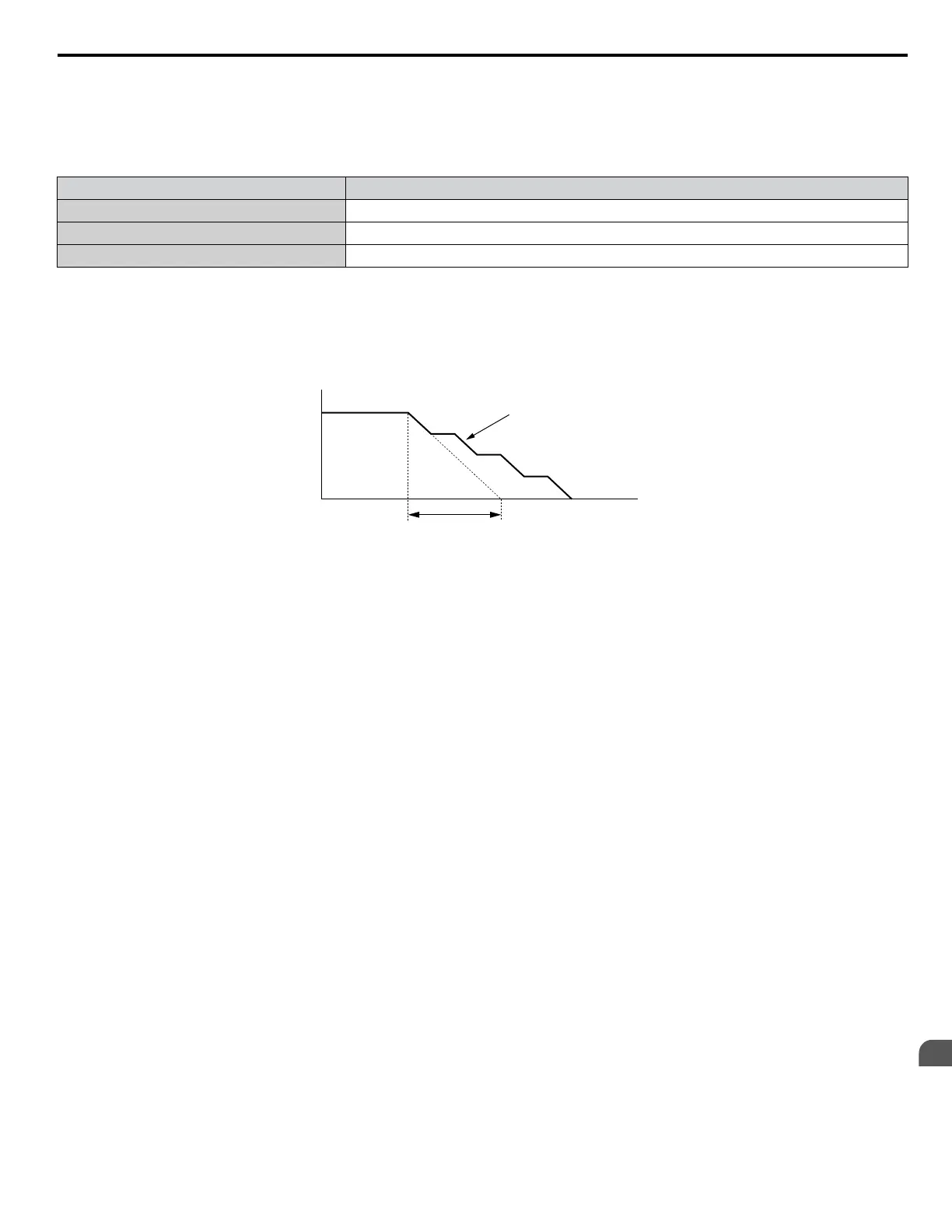
Figure 1.99 illustrates the function of Stall Prevention during deceleration.
Output Frequency
Deceleration characteristics
when Stall Prevention was
triggered during deceleration
Time
specified deceleration time
Figure 1.99 Stall Prevention During Deceleration
Setting 2: Intelligent Stall Prevention
The drive adjusts the deceleration rate so the DC bus voltage is kept at the level set to parameter L3-17. This produces the
shortest possible deceleration time while protecting the motor from stalling. The selected deceleration time is disregarded and
the achievable deceleration time cannot be smaller than 1/10 of the set deceleration time.
This function uses the following parameters for adjusting the deceleration rate:
• DC bus voltage gain (L3-20)
• Deceleration rate calculations gain (L3-21)
• Inertia calculations for motor acceleration time (L3-24)
• Load inertia ratio (L3-25)
Note: The deceleration time is not constant. Do not use Intelligent Stall Prevention in applications where stopping accuracy is a concern. Use
dynamic braking options instead.
Setting 3: Stall Prevention with dynamic braking option
Enables the Stall Prevention function while using a dynamic braking resistor. Overvoltage problems in the DC bus can occur
if Stall Prevention during deceleration is disabled (L3-04) in OLV and a dynamic braking option is installed. Set L3-04 to 3
to remedy this situation.
Setting 4: Overexcitation Deceleration 1
Overexcitation Deceleration 1 (increasing the motor flux) is faster than deceleration with no Stall Prevention (L3-04 = 0).
Setting 4 changes the selected decel time and functions to provide protection from an overvoltage trip. Refer to Overexcitation
Deceleration (Induction Motors) on page 159 for details.
Setting 5: Overexcitation Deceleration 2
Overexcitation Deceleration 2 slows down the motor while trying to maintain the DC bus voltage at the level set to parameter
L3-17. This function shortens the achievable deceleration time more than by using Overexcitation Deceleration 1. Setting 5
will shorten/lengthen the decel time to maintain the L3-17 bus level. Refer to Overexcitation Deceleration (Induction
Motors) on page 159 for details.
n
L3-05: Stall Prevention Selection during Run
Determines how Stall Prevention works during Run. Stall Prevention during run prevents the motor from stalling by
automatically reducing the speed when a transient overload occurs while the motor is running at constant speed.
1.8 L: Protection Functions
YASKAWA ELECTRIC SIEP YEAHHP 01B YASKAWA AC Drive – A1000 HHP Programming Manual
143
1
Parameter Details

 Loading...


