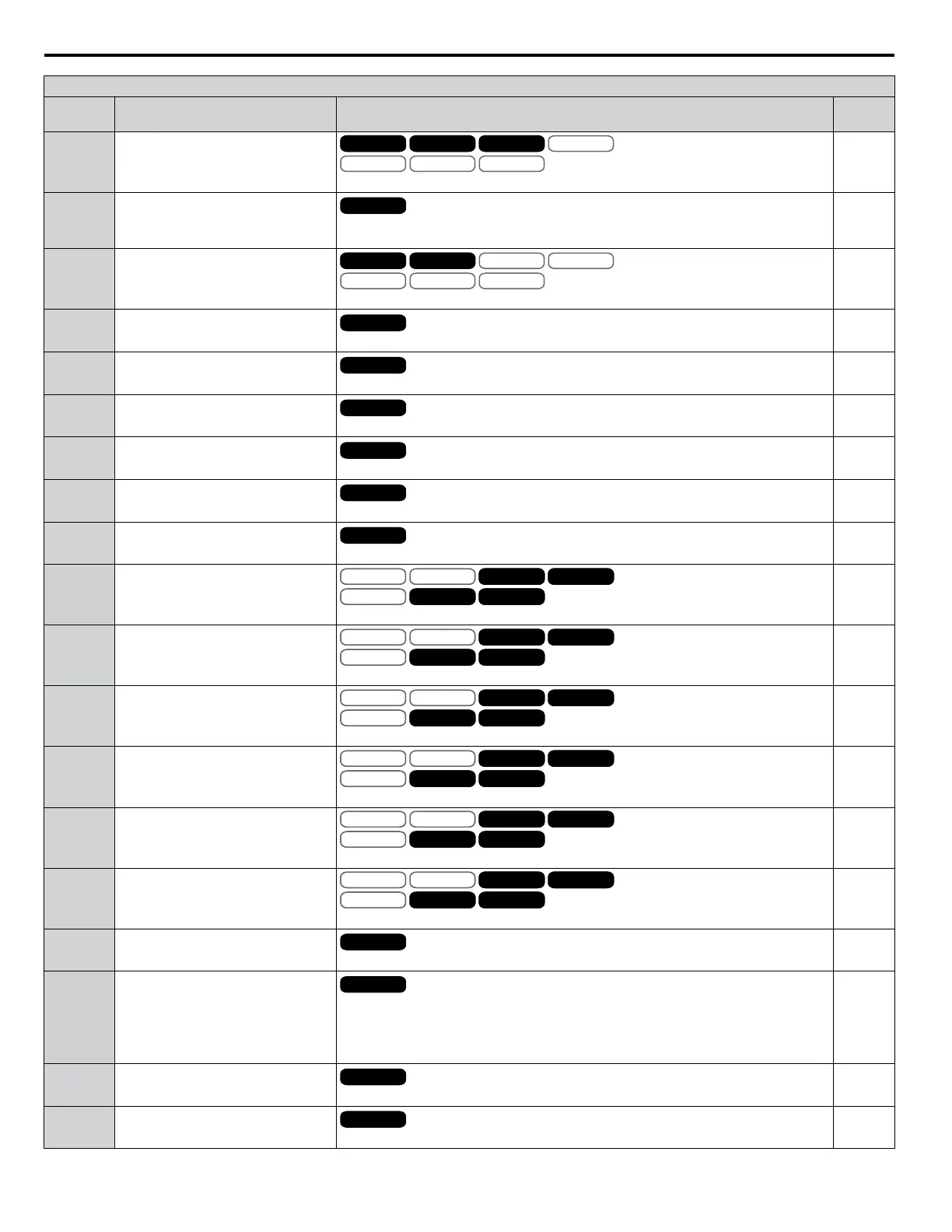
H3 Multi-Function Analog Input Settings
H3-oo
Setting
Function Description Page
6 DC Injection Braking current
V/f
OLV/PM
V/f w PG
AOLV/PM
OLV
CLV/PM
CLVV/f V/f w PG OLV
10 V = Drive rated current
119
7
Overtorque/undertorque
detection level
All Modes
10 V = Drive rated current (V/f, V/f w PG)
10 V = Motor rated torque (OLV, CLV, OLV/PM, AOLV/PM, CLV/PM)
119
8 Stall Prevention level during run
V/f
OLV/PM
V/f w PG
AOLV/PM
OLV
CLV/PM
CLVV/f V/f w PG
10 V = Drive rated current
120
9 Output frequency lower limit level
All Modes
10 V = E1-04 (maximum output frequency)
120
B PID feedback
All Modes
10 V = 100%
120
C PID setpoint
All Modes
10 V = 100%
120
D Frequency bias
All Modes
10 V = E1-04 (maximum output frequency)
120
E Motor temperature (PTC input)
All Modes
10 V = 100%
120
F Through mode
All Modes
Set this value when using the terminal in the pass-through mode.
120
10 Forward torque limit
V/f
OLV/PM
V/f w PG
AOLV/PM
OLV
CLV/PM
CLV
AOLV/PM
OLV
CLV/PM
CLVV/f
OLV/PM
V/f w PG
AOLV/PM
OLV
CLV/PM
CLV
AOLV/PM
OLV
CLV/PM
CLV
10 V = Motor rated torque
120
11 Reverse torque limit
V/f
OLV/PM
V/f w PG
AOLV/PM
OLV
CLV/PM
CLV
AOLV/PM
OLV
CLV/PM
CLVV/f
OLV/PM
V/f w PG
AOLV/PM
OLV
CLV/PM
CLV
AOLV/PM
OLV
CLV/PM
CLV
10 V = Motor rated torque
120
12 Regenerative torque limit
V/f
OLV/PM
V/f w PG
AOLV/PM
OLV
CLV/PM
CLV
AOLV/PM
OLV
CLV/PM
CLVV/f
OLV/PM
V/f w PG
AOLV/PM
OLV
CLV/PM
CLV
AOLV/PM
OLV
CLV/PM
CLV
10 V = Motor rated torque
120
13 Torque reference/Torque limit
V/f
OLV/PM
V/f w PG
AOLV/PM
OLV
CLV/PM
CLV
AOLV/PM
OLV
CLV/PM
CLVV/f
OLV/PM
V/f w PG
AOLV/PM
OLV
CLV/PM
CLV
AOLV/PM
OLV
CLV/PM
CLV
10 V = Motor rated torque
120
14 Torque compensation
V/f
OLV/PM
V/f w PG
AOLV/PM
OLV
CLV/PM
CLV
AOLV/PM
OLV
CLV/PM
CLVV/f
OLV/PM
V/f w PG
AOLV/PM
OLV
CLV/PM
CLV
AOLV/PM
OLV
CLV/PM
CLV
10 V = Motor rated torque
120
15 General torque limit
V/f
OLV/PM
V/f w PG
AOLV/PM
OLV
CLV/PM
CLV
AOLV/PM
OLV
CLV/PM
CLVV/f
OLV/PM
V/f w PG
AOLV/PM
OLV
CLV/PM
CLV
AOLV/PM
OLV
CLV/PM
CLV
10 V = Motor rated torque
120
16 Differential PID feedback
All Modes
10 V = 100%
120
17 Motor Thermistor (NTC)
All Modes
10 V = -9 °C
0 V = 234 °C
Note:
This function is only available in models CIMR-Ao4A0930, 4A1200 and
A1000 HHP.
120
1F Through mode
All Modes
Set this value when using the terminal in the pass-through mode.
120
30 to 32
DriveWorksEZ
analog input 1 to 3
All Modes
Output is determined by the function selected using DWEZ.
120
A.9 H Parameters: Multi-Function Terminals
278
YASKAWA ELECTRIC SIEP YEAHHP 01B YASKAWA AC Drive – A1000 HHP Programming Manual

 Loading...


