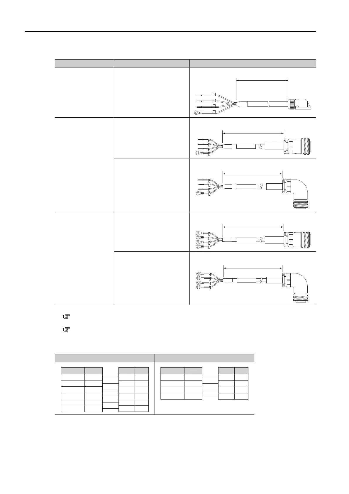
6.2 Servomotor Main Circuit Cables
6.2.1 Servomotor Main Circuit Cables for Servomotors without Holding Brakes
6-6
External Dimensions
*1. Refer to the following section for information on connector manufacturers and order numbers.
6.3.1 Servomotor Connector Kits for 300 W or 450 W
on page 6-11
*2. Refer to the following section for information on connector manufacturers and order numbers.
6.3.3 Standard-Structure Servomotor Connectors for 850 W to 15 kW
on page 6-12
Wiring Specifications
Servomotor Model Connector Specifications External Dimensions
SGM7G-03 or -05
300 W or 450 W
*1
SGM7G-09 or -13
850 W or 1.3 kW
MS connector, straight
*2
MS connector, right-angle
*2
SGM7G-20 to -1E
1.8 kW to 15 kW
MS connector, straight
*2
MS connector, right-angle
*2
300 W, 450 W 850 W to 15 kW
SERVOPACK end Motor end
L
L
SERVOPACK end Motor end
L
SERVOPACK end Motor end
L
SERVOPACK end Motor end
L
SERVOPACK end Motor end
PinSignal
SignalWire Color
PE
5
4
3
2
1
Servomotor Connecto
Phase U
−
−
FG
Phase V
Phase W
Phase U
−
−
FG
Red
Phase VWhite
Phase WBlue
−
−
Green/yellow
SERVOPACK Leads
PinSignal
SignalWire Color
A
B
C
D
Servomotor Connector
FG
Phase W
Phase V
Phase U
FG
Phase W
Phase V
Phase U
Green/yellow
Blue
White
Red
SERVOPACK Leads