4.2 Servomotor Main Circuit Cables
4.2.2 Servomotor Main Circuit Cables for Servomotors with Holding Brakes
4-8
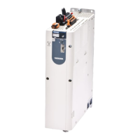
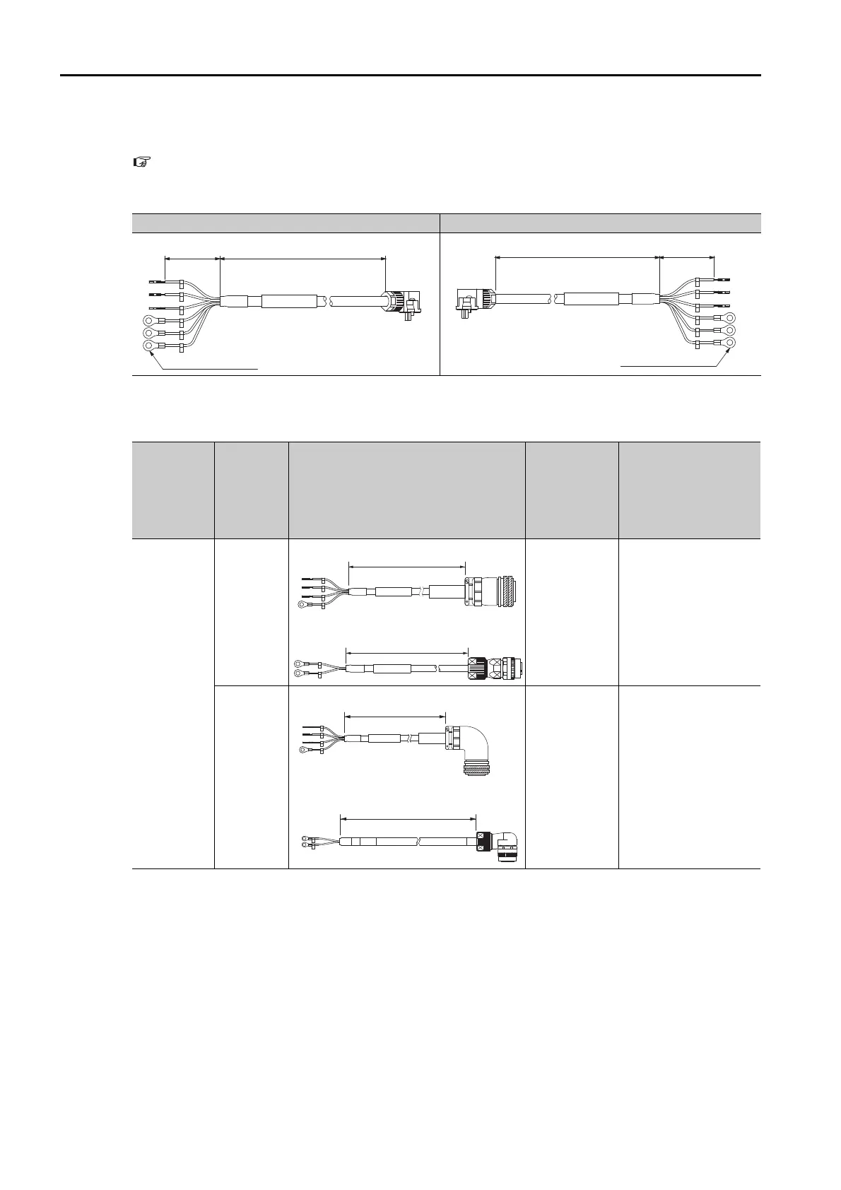
External Dimensions
Note: Refer to the following section for information on connector manufacturers and order numbers.
4.3 User-Assembled Wiring Materials for Servomotor Main Circuit Cables on page 4-11
SGM7A-A5 to -10 (50 W to 1.0 kW)
SGM7A-15 to -50 (for 1.5 kW to 5.0 kW)
Cable Installed away from Load Cable Installed toward Load
Servomotor
Model
Connector
Typ e
External Dimensions
Order Num-
bers of Main
Power Sup-
ply Cable and
Holding Brake
Cable
Individual Cable Order
Numbers
SGM7A-15
1.5 kW
Straight
Standard
Cable:
JZSP-
UVA131--
E
Flexible Cable:
JZSP-
UVA141--
E
• Main Circuit Power
Supply Cable
Standard Cable:
JZSP-UVA101-
-E
Flexible Cable:
JZSP-UVA121--E
• Holding Brake
Cable
*2
JZSP-U7B23--E
Right-
angle
*1
Standard
Cable:
JZSP-
UVA132--
E
Flexible Cable:
JZSP-
UVA142--
E
• Main Circuit Power
Supply Cable
Standard Cable:
JZSP-UVA102-
-E
Flexible Cable:
JZSP-UVA122--E
• Holding Brake
Cable
*2
JZSP-U7B24--E
Continued on next page.
*1. The lead installation direction is away from the load.
*2. Flexible Cables are provided as a standard feature.
SERVOPACK end Motor end
U
V
W
G
B
B
50 mm
L
M4 crimped terminal
SERVOPACK endMotor end
U
V
W
G
B
B
50 mmL
M4 crimped terminal
L
SERVOPACK end Motor end
L
SERVOPACK end Brake end
L
Brake end Motor end
L
SERVOPACK end Motor end