3.2 Servomotor Main Circuit Cables
3.2.2 Servomotor Main Circuit Cables for Servomotors with Holding Brakes
3-4
3.2.2
Servomotor Main Circuit Cables for Servomotors with
Holding Brakes
Selection Table
*1. Replace the boxes () in the order number with the cable length (03, 05, 10, 15, 20, 30, 40, or 50).
*2. Use Flexible Cables for moving parts of machines, such as robots.
*3. The recommended bending radius (R) is 90 mm or larger.
Note: If the length of the Servomotor Main Circuit Cable exceeds 20 m, the intermittent duty zone in the torque-
motor speed characteristics will become smaller because the voltage drop increases.
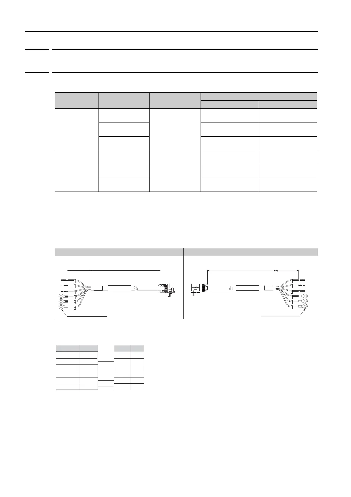
Lead Structure
Wiring Specifications
Note: There is no polarity for the connection to the holding brake.
Cable Direction Servomotor Model Length (L)
Order Number
*1
Standard Cable Flexible Cable
*2, *3
Load side
SGM7J-A5 to -C2
50 W to 150 W
3 m, 5 m, 10 m,
15 m, 20 m, 30 m,
40 m, and 50 m
JZSP-C7M13F-
-E JZSP-C7M14F--E
SGM7J-02 to -06
200 W to 600 W
JZSP-C7M23F-
-E JZSP-C7M24F--E
SGM7J-08
750 W
JZSP-C7M33F-
-E JZSP-C7M34F--E
Non-load side
SGM7J-A5 to -C2
50 W to 150 W
JZSP-C7M13G-
-E JZSP-C7M14G--E
SGM7J-02 to -06
200 W to 600 W
JZSP-C7M23G-
-E JZSP-C7M24G--E
SGM7J-08
750 W
JZSP-C7M33G-
-E JZSP-C7M34G--E
Cable Installed away from Load Cable Installed toward Load
SERVOPACK end Motor end
U
V
W
G
B
B
50 mm
L
M4 crimped terminal
SERVOPACK endMotor end
U
V
W
G
B
B
50 mmL
M4 crimped terminal
PinSignal
SignalWire Color
1
2
3
4
5
6
Servomotor Connector
Phase U
Phase V
Phase W
FG
Brake
Brake
Brake
Brake
Phase U
Phase V
Phase W
FG
Red
White
Blue
Green/yellow
Black
Black
SERVOPACK Leads