9.4 Serial Converter Unit
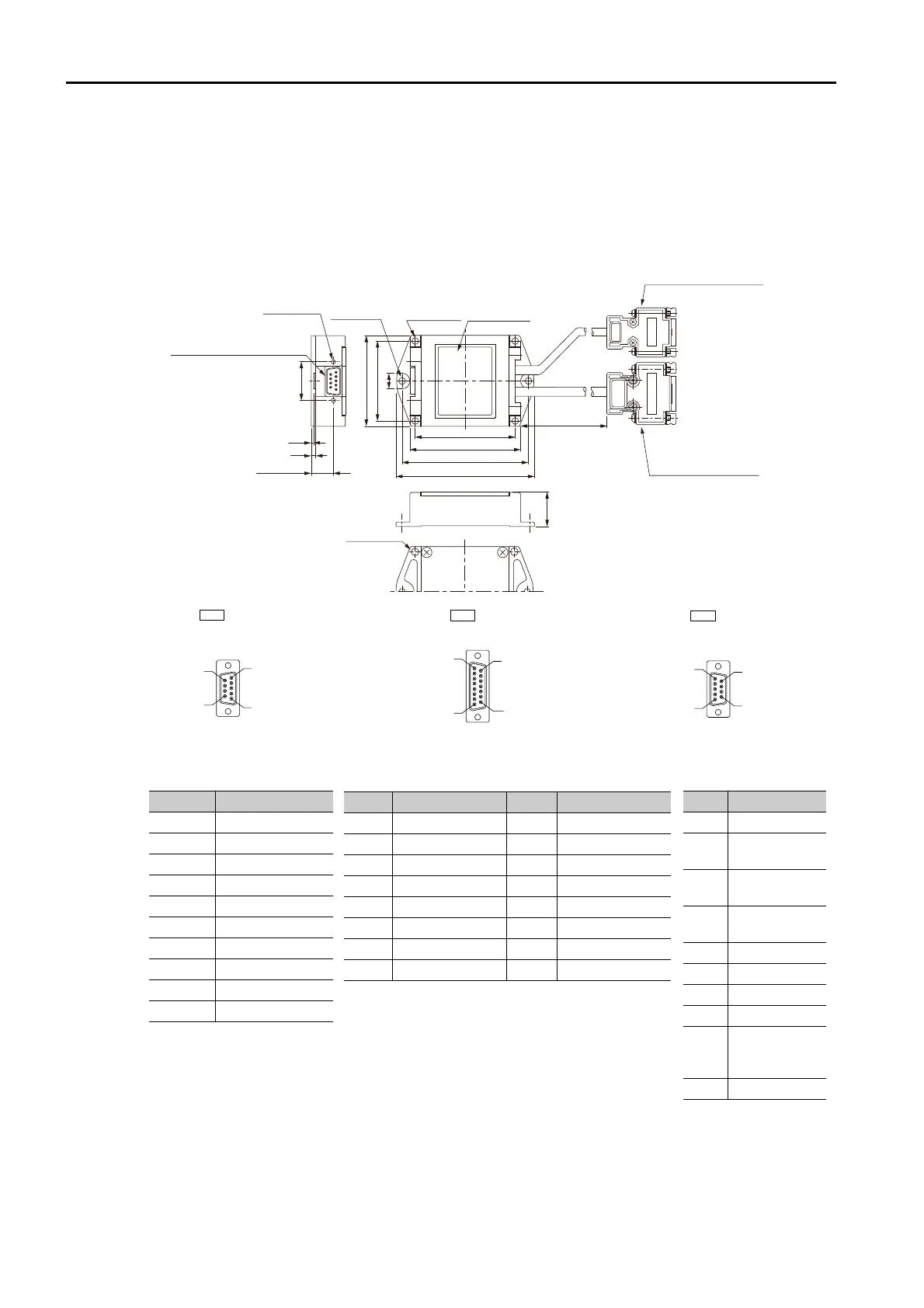
9.4.3 External Dimensions
9-34
Serial Converter Unit with Polarity Sensor Cable
(for Linear Encoder from Dr. JOHANNES HEIDENHAIN
GmbH)
Model: JZDP-
006-
Note: 1. Do not connect the unused pins.
2. Contact Dr. JOHANNES HEIDENHAIN GmbH for details on cables (analog 1 Vp-p output, D-sub 15-pin,
male) from Dr. JOHANNES HEIDENHAIN GmbH.
3. The phase U, V, and W inputs are internally pulled up with 10 kΩ.
22.5
82 0.3
52 0.3
65 0.3
72
90
60
10
1.5
3
14.35 0.4
24.99 0.4
300 30
Unit: mm
4 × M5 × 10
Linear Encoder-end
analog signal input
connector (CN2)
Linear Servomotor-end
polarity sensor signal input
connector (CN3)
2 × 4.2 dia. holes
4 × 4.2 dia. holes
Nameplate
2 × #4-40
UNC screws
SERVOPACK-end serial data
output connector (CN1)
9
6
1
5
CN1
17-Series Connector:
17LE-13090-27-FA
from DDK Ltd.
(Socket)
SERVOPACK-end
serial data outputs
1
8
9
15
CN2
Linear Encoder-end
analog signal inputs
17-Series Connector:
17JE-13150-02 (D8C) A-CG
from DDK Ltd.
(Socket)
9
6
1
5
CN3
Linear Servomotor-end
polarity sensor signal input
17-Series Connector:
17JE-13090-02 (D8C) A-CG
from DDK Ltd.
Pin Signal
1+ 5 V
2Phase-S output
3Not used
4Not used
50 V
6 /Phase-S output
7Not used
8Not used
9Not used
Case Shield
Pin Signal Pin Signal
1cos input (A+) 9/cos input (A-)
20 V 100 V sensor
3 sin input (B+) 11 /sin input (B-)
4 + 5 V 12 5 V sensor
5 Not used 13 Not used
6Not used 14Ref input (R+)
7 /Ref input (R-) 15 Not used
8 Not used Case Shield
Pin Signal
1+5 V
2
Phase-U
input
3
Phase-V
input
4
Phase-W
input
50 V
6Not used
7Not used
8Not used
9
Thermal
protector
input
Case
Shield

 Loading...


