App-7
IM 765501-01E
Appendix
3
2
1
6
5
4
9
8
7
12
11
10
15
14
13
18
17
16
Index
App
Procedure
Preparation
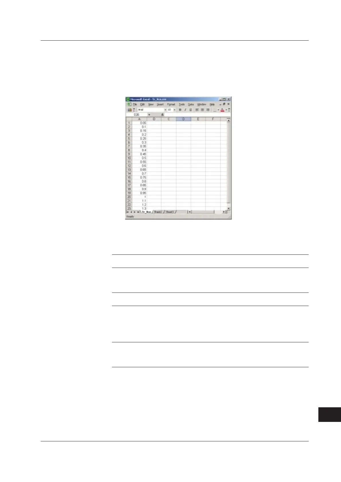
1. Create a sweep pattern (source pattern) used to vary collector-emitter voltage
V
CE
of the transistor using a general-purpose spreadsheet application on your
PC. (If the amount of voltage change is constant, you can also use the linear
sweep (see section 6.1, “Setting the Log or Linear Sweep”).)
2. Save the pattern sweep data that you created in step 1 to a file in CSV format.
3. Transfer (Copy) the pattern sweep data file to the internal memory
(GS610ROM) of the first GS610 via the USB.
4. Set each GS610 as follows:
Setup Example of Setup Example of
the First GS610 the Second GS610
SOURCE Output function Voltage output Current output
Limiter value 150 mA 1 V
Output mode DC DC
Output range: AUTO AUTO
OUTPUT CONTROL Trigger mode Internal Internal
Sweep mode Program OFF
MEASURE Measurement function ON OFF
Measurement function Current measurement –
Integration time 200 ms –
Measurement range AUTO –
Auto store ON –
Store ON –
TIME Source delay 1 µs–
Measurement delay 1 ms –
Repeat period 500 ms –
(of the internal trigger)*
*
Repeat period of the internal trigger > Output delay + measure delay + integration time + α.
(α = Time caused by range change, calibration, and so on)
Appendix 2 Application Examples
 Loading...


