App-9
IM 765501-01E
Appendix
3
2
1
6
5
4
9
8
7
12
11
10
15
14
13
18
17
16
Index
App
• I
B
-I
C
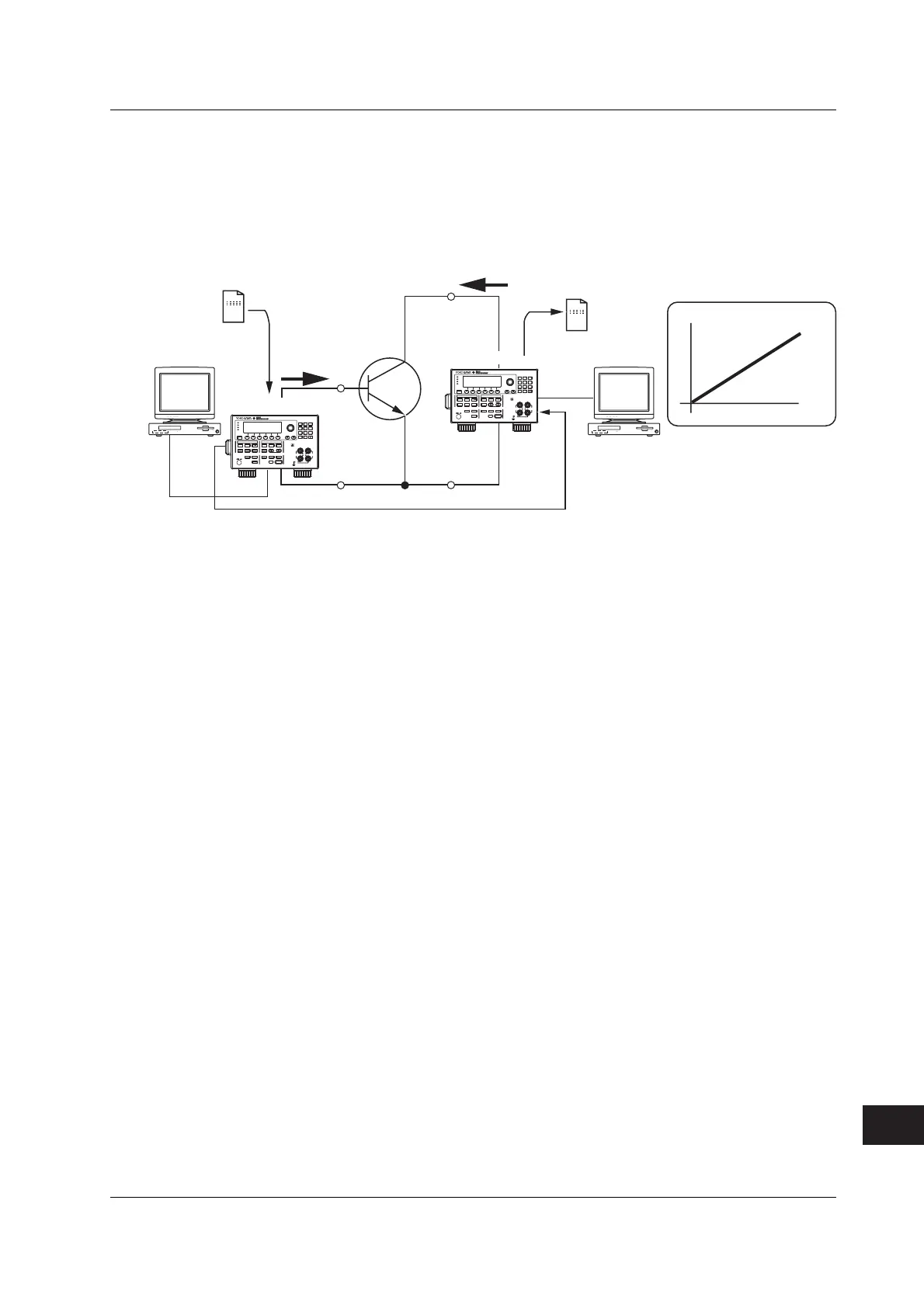
Characteristics Evaluation
The I
B
-I
C
characteristics of a transistor can be measured by synchronizing two GS610s.
Details of Operation
Measures collector current I
c
when base current I
B
is varied with collector-emitter voltage
V
CE
fixed using two synchronized GS610s.
Ic
0
V
CE
= Constant
PCPC
Result file
Sweep
pattern
file
E
B
E
C
AVERAGE
4 WIRE
KEY LOCK
DISPLAY
ESC
MEASURE
STORE
AUTO
RANGE
MENU
REGALL
MATH
NULL
COMPARE
MEASURE
VALUE
REMOTE
LOCAL
POWER
MISC
TIME
KEY LOCK
SHIFT
MODE
AUTO
RANGE
LIMIT
MENU
SOURCE
RANGE
OUTPUT CONTROL
SWEEP
START
ZERO
SOURCE
TRIG
MODE
OUTPUT
BS
SENSE
OUTPUT
Hi
110V
MAX
1V
MAX
110V
MAX
Lo
250V
MAX
789
456
123
0
.
+
-
GS610 No.1
AVERAGE
4 WIRE
KEY LOCK
DISPLAY
ESC
MEASURE
STORE
AUTO
RANGE
MENU
REGALL
MATH
NULL
COMPARE
MEASURE
VALUE
REMOTE
LOCAL
POWER
MISC
TIME
KEY LOCK
SHIFT
MODE
AUTO
RANGE
LIMIT
MENU
SOURCE
RANGE
OUTPUT CONTROL
SWEEP
START
ZERO
SOURCE
TRIG
MODE
OUTPUT
BS
SENSE
OUTPUT
Hi
110V
MAX
1V
MAX
110V
MAX
Lo
250V
MAX
789
456
123
0
.
+
-
GS610 No.2
USB
USB
I
B
I
C
I
B
Synchronization operation control signal
Connection example for measurements
Key Points in the Operation and Setting
• Synchronizing two GS610s: See section 10.2, “Synchronized Operation.”
• Transferring the pattern files and measurement result data files using the USB storage
function: See section 6.6, “Program Pattern File” and 4.3, “USB Storage Function.”
• Saving the measurement result data using the storage function: See section 9.1,
“Storing the Measured Results.”
Connection Procedure
1. Connect the first GS610 between the collector and the emitter of the transistor.
2. Connect the second GS610 between the base and the emitter of the transistor.
3. Connect TRIG IN on the rear panel of the first GS610 to TRIG OUT on the rear
panel of the second GS610 (see section 10.2, “Synchronized Operation.”).
4. Connect each GS610 to a PC using a USB cable (see section 4.3, “USB
Storage Function).
Appendix 2 Application Examples
 Loading...


