Technical Specifications A - 5
I/O Connector Pin-Outs
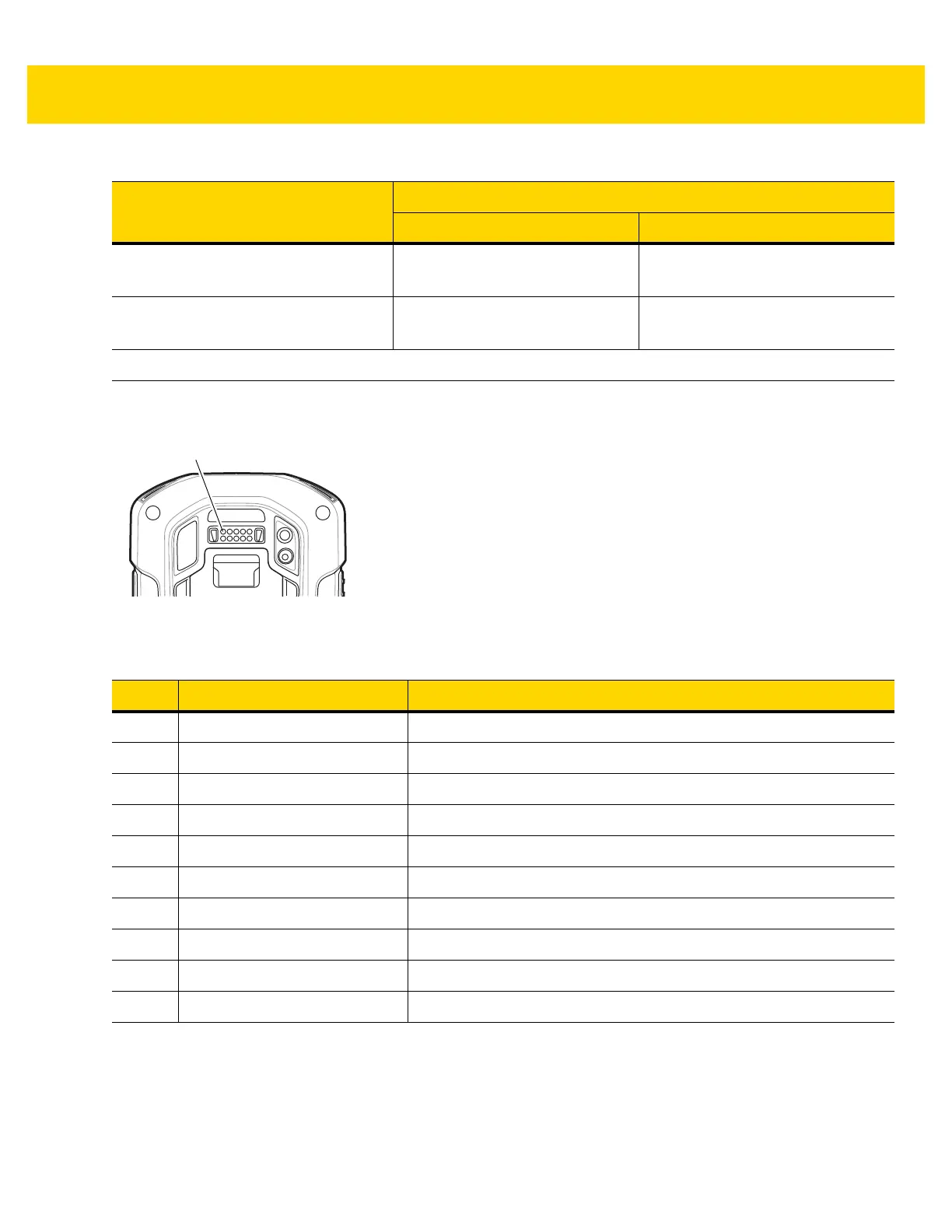
Figure A-1 I/O Connector
15 mil Code 128 2.6 in.
6.06 cm
19.8 in.
50.29 cm
20 mil Code 39 1.8 in.
4.57 cm
27.0 in.
68.58 cm
Note: Photographic quality bar code at 18° tilt pitch angle under 30 fcd ambient illumination.
Table A-3 SE4750-SR Decode Distances
Symbol Density/ Bar Code Type
Typical Working Ranges
Near Far
Table A-4 I/O Connector Pin-Outs
Pin Signal Description
1 GND Power/signal ground.
2 RXD_MIC UART RXD + Headset microphone.
3 PWR_IN_CON External 5.4 VDC power input.
4 TRIG_PTT Trigger or PTT input.
5 GND Power/signal ground.
6 USB-OTG_ID USB OTG ID pin.
7 TXD_EAR UART TXD, Headset ear.
8 USB_OTG_VBUS USB VBUS
9USB_OTG_DP USB DP
10 USB_OTG_DM USB DM
 Loading...
