2 - 50 TC70x Integrator Guide
2. Route the power input cable from the USB I/O Hub’s power port to the connection point for the vehicle’s power
source.
3. When using the supplied in-line fuse holder (which must be used if not connecting to vehicle’s fuse panel):
a. Ensure the fuse holder contains a 5A UL Listed slow-blow fuse.
b. Splice the fuse holder to the end of the red V+ wire, as shown below. Make the distance from the fuse to
the power connection point as short as possible.
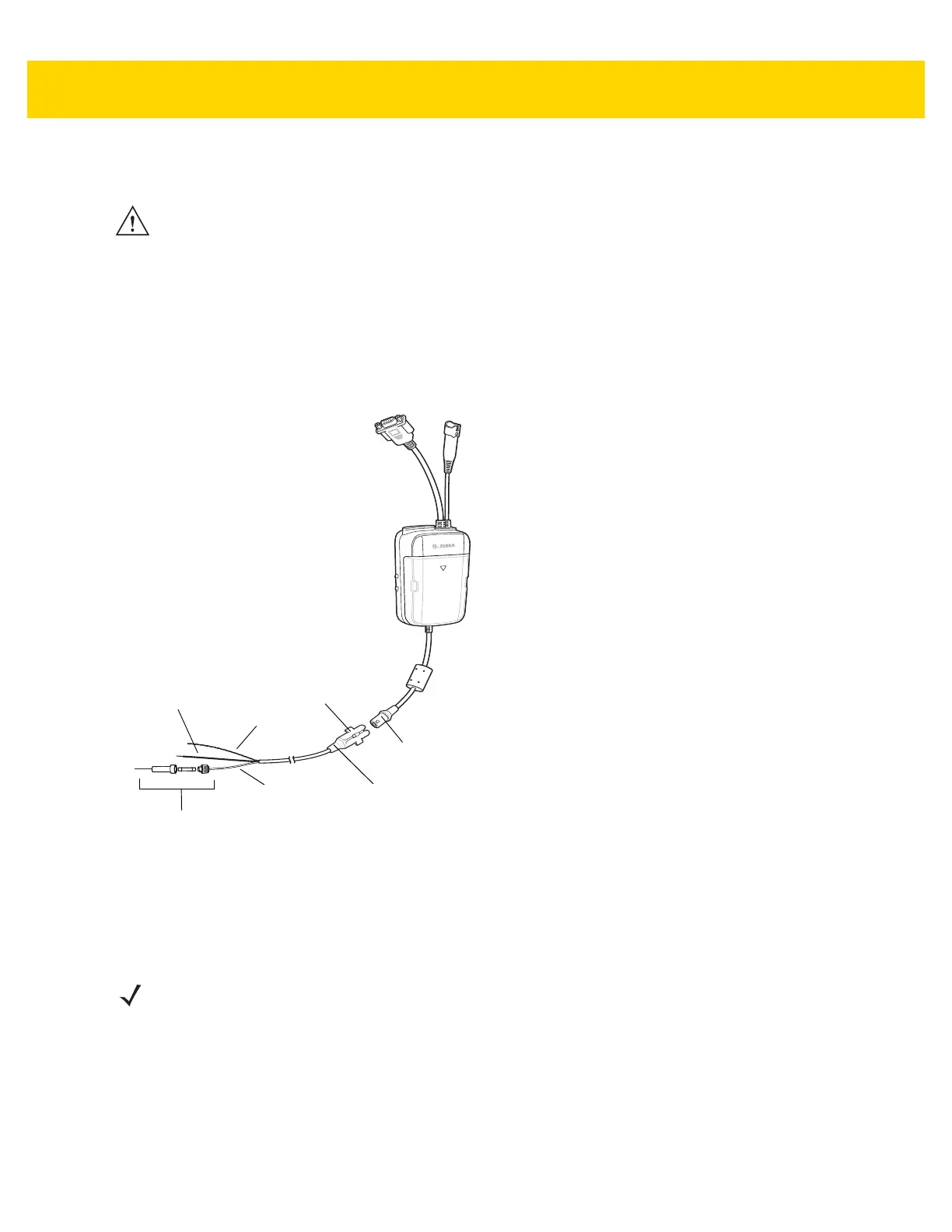
Figure 2-66 Hard Wired Power Connection
4. Prepare the cable termination.
a. Red wire: connect to a +12/24 V vehicle power source.
b. Black wire and Shield wire: connect to vehicle ground wire or chassis ground.
5. Ensure that the connector collar is installed on the connector.
6. Connect the power connector to the power Input Connector on the USB I/O Hub.
To see if the USB I/O Hub has power, connect to a vehicle cradle and insert a device into the cradle. The Charging
LED on the device indicates charging. See the device User Guide for charging indications.
NOTEThe means of routing and securing the power input cable from the USB I/O Hub through to the vehicle power source is
extremely important. Hazards associated with improper wiring can be severe. To avoid unintentional contact between the wire
and any sharp edges, provide the cable with proper bushings and clamping where it passes through openings. If the wire is
subjected to sharp surfaces and excess engine vibration, the wiring harness insulation can wear away, causing a short
between the bare wire and chassis. This can start a fire. To avoid any mishaps, all wiring should be routed away from moving
parts, high temperature areas and any contaminants.
NOTE How the cable terminates depends on the vehicle. If the vehicle has a power output connector, then you must
attach a mating connector to the end of the power cable. You may be able to connect to a fuse panel with a
simple blade terminal or commercially available connector. Consult the vehicle Owner’s Manual for information
on how to access the power supply in the vehicle.
Shield
Wire (bare
wire)
Ground
Wire
(black)
V+ Power (red)
5A Fuse and In-line
Fuse Holder (optional)
Power Input
Connector
Power Connector
Collar
 Loading...
