START-UP
Carl Zeiss Installing standard components Axio Examiner
34 M60-2-0003 e 05/2012
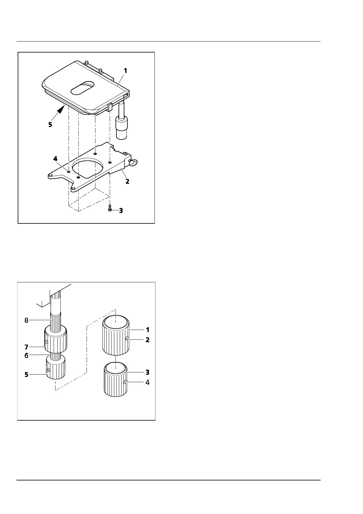
3.1.11 Installing the mechanical stage on
the stage carrier
• Put the stage (Figure 3-14/1) on the stage
carrier (Figure 3-14/2), aligning the four
threaded boreholes in the lower table side
(Figure 3-14/5) above the through holes
(Figure 3-14/4) of the stage carrier.
• Insert the four fastening screws (Figure 3-14/3)
from below through the stage carrier, and
screw them into the stage bottom side.
• Align the stage in XY direction, and tighten the
fastening screws.
Readjusting the drive length at 3.1.11.1
the ergonomic drive
At mechanical stages provided with an ergonomic
drive, the drive length for X and Y axis positioning
may be increased by a maximum of 15 mm by
displacing the pinion knobs in axial direction.
Removing or installing additional 3.1.11.2
sleeves
Both pinion knobs are provided with additional
sleeves. They allow an even more sensitive setting
of object positions. But they can be removed if it is
more important to be able and move the objects
quicker.
• First unscrew the two clamping screws
(Figure 3-15/4) of the lower additional sleeve
(Figure 3-15/3), and pull it off downwards, then
unscrew the two clamping screws
(Figure 3-15/2) of the upper additional sleeve
(Figure 3-15/1), and also pull it off downwards.
• Put the additional sleeves in reverse order onto
the pinion knobs again, and tighten both
clamping screws.
Figure 3-14 Installing the mechanical stage on
the stage carrier
Figure 3-15 Setting the ergonomic drive