OPERATION
Carl Zeiss Controls and functional elements for optional components Axio Examiner
80 M60-2-0003 e 05/2012
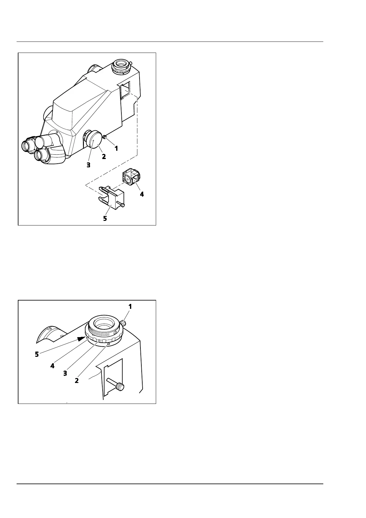
4.4.3 Binocular phototube zoom 0.5 – 4x
with a P&C module mount
The binocular zoom phototube (425521-9000-
000) has a zoom knob (Figure 4-21/2) for zooming
an image either in or out.
The actuating rod (Figure 4-21/1) may be used to
switch over from visual observation to
photomicrography.
The phototube has two camera ports, allowing
simultaneous picture recording. The holder
(Figure 4-21/5) may be loaded with P&C modules
(Figure 4-21/4). If no module is in the holder, the
image will only be mirrored out through the upper
camera port.
(1) Click-stop setting
The zoom knob click stop may be switched off:
• To switch off the click stop, turn the adjusting
screw (Figure 4-21/3) at the zoom knob
(Figure 4-21/2) by 90°.
• To enable the click stop again, rotate the
adjusting screw (Figure 4-21/3) by 90° in the
opposite direction.
(2) Adjusting the cameras to one another
If two cameras are used, they need to be adjusted
to one another in order to obtain identical images
(size, detail). Please proceed as follows:
• Connect the cameras to the phototube.
• Insert the holder (Figure 4-21/5) with the P&C
module.
• Set the actuating rod (Figure 4-21/1) to
photomicrography.
• Focus on the object using the side-mounted
camera.
• Undo the screw (width A/F 1.5) (Figure 4-22/3)
at the knurled ring (Figure 4-22/4) of the upper
camera port.
• Turn the knurled ring (Figure 4-22/4) until the
upper camera's Z position is adjusted to the
side-mounted camera.
• Tighten the screw (Figure 4-22/3) again. The Z
axis is adjusted now.
1 Actuating rod
2 Zoom knob
3 Adjusting screw
4 P&C module
5 Holder
Figure 4-21 Binocular phototube zoom 0.5 – 4x
with a P&C module mount
1 Knurled screw
2 X-Y adjusting screw
3 Screw
4 Knurled ring
5 X-Y adjusting screw
Figure 4-22 Adjusting a camera