START-UP
Carl Zeiss Installing optional components Axio Examiner
52 M60-2-0003 e 05/2012
3.3.6 Replacing the beam splitter in the FL P&C reflector module
To avoid any damage or contamination of o
ptical elements, proceed with utmost care when
installing filters and the beam splitter.
We recommend ordering fully equipped FL P&C reflector modules as beam splitter replacement is more
demanding.
Otherwise, please proceed as described below:
• Remove the FL P&C reflector module from the
reflector turret (see section 3.1.5).
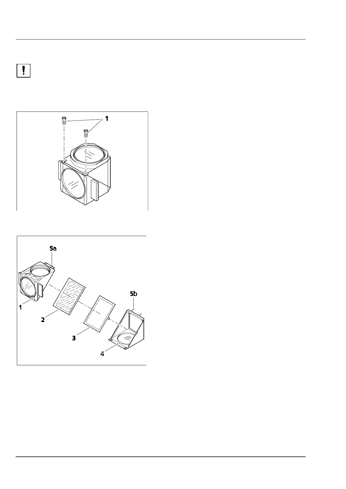
• Unscrew the two slotted screws (Figure 3-37/1)
using a screwdriver.
• Hold both reflector module halves together,
turn them around opposite to the mounting
position, and lay them down.
• Tilt the upper half module (Figure 3-38/1)
upwards, and lift it out of the holder elements
(Figure 3-38/5b) of the lower half module.
• Take beam splitter (Figure 3-38/2) and spring
frame (Figure 3-38/3) out of the lower half
module.
• Remove the old beam splitter, and position the
new beam splitter with the reflecting side
pointing down onto the spring frame
(Figure 3-38/4), and lay both parts together into
the lower half module. Please make certain that
the lateral spring frame tab is located in the
corresponding recess at the lower half module.
The reflecting side of the beam splitter is shown by
the fact that no distance between a small wood
stick and its mirror image is seen when a small
wood stick is placed on the beam splitter surface.
• Place the upper half module (Figure 3-38/1)
onto the lower half module (Figure 3-38/4)
(holder elements Figure 3-38/5b will engage
into the eyes Figure 3-38/5a). Hold both halves
together, and turn them back into the
mounting position again.
• Insert and tighten the slotted screws again.
• Finally, attach an adhesive label indicating the
designation of the filter combination to a
module side.
Figure 3-37 Opening a beam splitter
Figure 3-38 Replacing a beam splitter