START-UP
Axio Examiner Installing optional components Carl Zeiss
M60-2-0003 e 05/2012 49
3.3 Installing optional components
Before starting any work, pull out the power plugs of the external power supply units.
After completing conversion, the corresponding assemblies need to be restored to a functional
condition again (see sections 3.1 to 1.1).
For information on the possible combinations between the various components and with the
various upper microscope parts stands, please refer to the System Overview (see page 19 and the
following).
3.3.1 Replacing the stand top part
replace and inserting an adapter
for extending the specimen area
Please note that the Axio Examiner.Z1 stand
top part may only be used in combination
with the motor-operated stand.
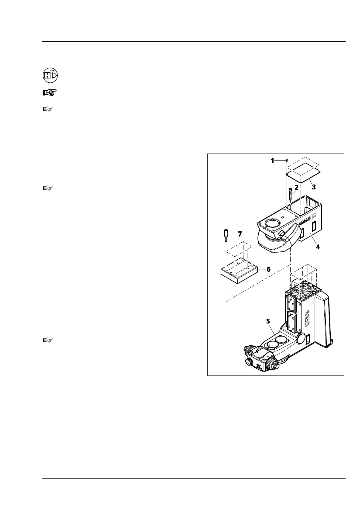
• Unscrew the four fastening screws
(Figure 3-32/1) which hold the cover.
• Remove the cover (Figure 3-32/3) from the
stand top part. To do so, insert a screwdriver
into the assembly opening located at the front
side, and use it to lift off the cover.
• Hold the stand top part (Figure 3-32/4) in
position, screw out the six hexagon socket head
screws (Figure 3-32/2), and remove the stand
top part.
• If an adapter (Figure 3-32/6) should be installed,
screw the spacer sleeves (Figure 3-32/7) into the
stand bottom part, and put on the 30 mm
adapter.
To be able and use the adapter, the objective
mount or the objective nosepiece and the
stage carrier need to be pushed against the
corresponding upper stop screw of the
dovetail guide. See sections 3.1.7 and 3.1.12.
• Position the stand top part (Figure 3-32/4) to be
installed onto the lower stand part
(Figure 3-32/5) or on the adapter, hold it in
position, and screw it down by tightening the
six hexagon socket head screws (Figure 3-32/2).
• Put on the cover (Figure 3-32/3) again.
• Screw in and tighten the four cover fastening screws (Figure 3-32/1).
• Check the installation positions of objective mount or objective nosepiece and stage carrier, and
modify if required (see section 3.1.7 and 3.1.12).
Figure 3-32 Replacing the stand top part,
inserting an adapter