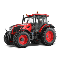
Description of the functions of individual positions of control levers of the hydraulic distributo
FH12N049
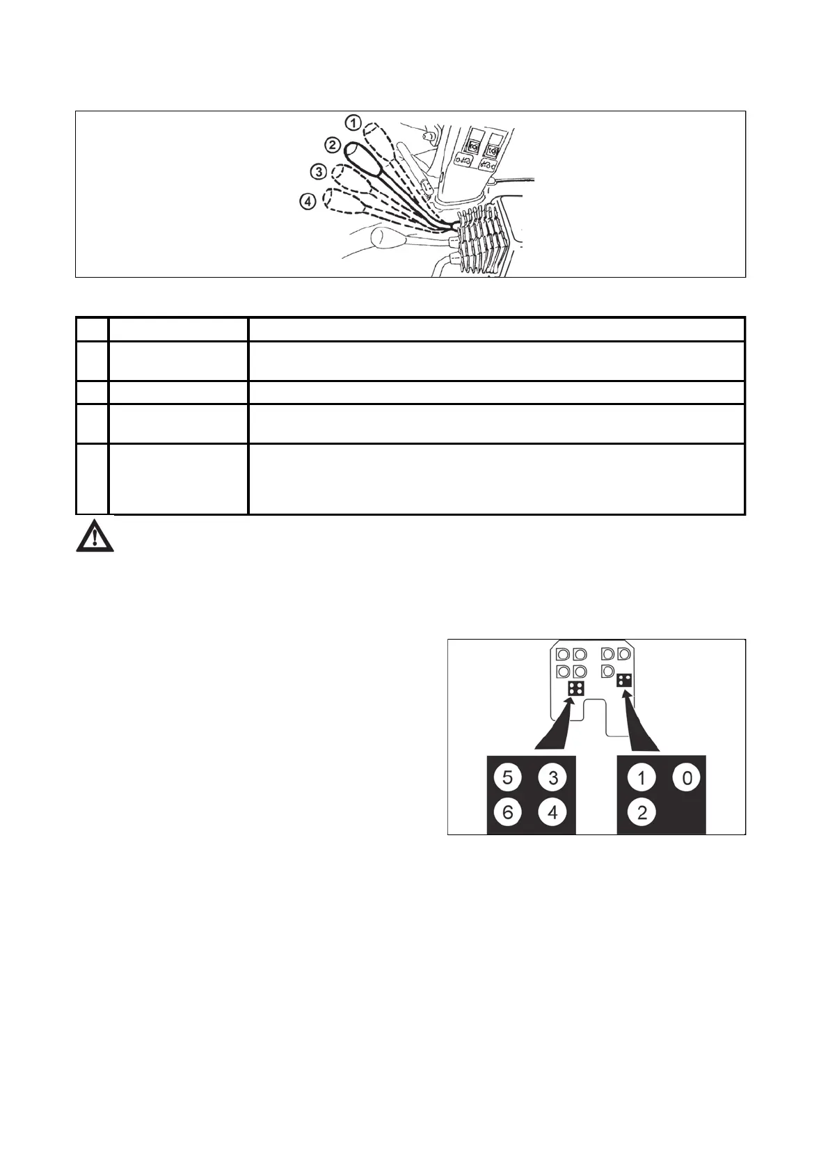
Always connect a single-acting cylinder to quick couplers:
'2', '4' of the two-section auxiliary distributor and
'2', '4', '6' of the three-section auxiliary distributor.
lwa
s connect a doubl
-acting cylinder to quick-couplers of one section.
Rear outlets of the outer hydraulic circuit
Lever position Function
1 Rear (upper)
position
Pressurized oil flows to quick-couplers: '2', '4', '6'
Quick-couplers connected to the return line: '1', '3', '5'
2 Central position Neutral
3 Front (lower)
position
Pressurized oil flows to quick-couplers: '1', '3', '5'
Quick-couplers connected to the return line: '2', '4', '6'
4 Front limit position With an increased force you can shift the control levers from position (3) further
to the front to position (4), i.e. floating (free) position, where the levers are
locked. Both the quick-couplers of each section are connected to the return line
in this position.
In the tractor version that is not equipped with the front
outlets or the front three-point hitch and that is equipped
with:
a - a three-section distributor the rear outlets are
terminated with pressure quick-couplers '1' to '6'.
b - a two-section distributor the rear outlets are terminated
with pressure quick-couplers '1' to '4'.
The third quick-coupler marked '0' is directly connected to
the final drive housing and is designed for return oil from
external hydraulic implements (e.g. from rotational
hydraulic motors, etc.).
FH12N044a
 Loading...