3-16 (26) 2UEA001270 Rev. F ACS2000 User manual
Chapter 3 - Control system
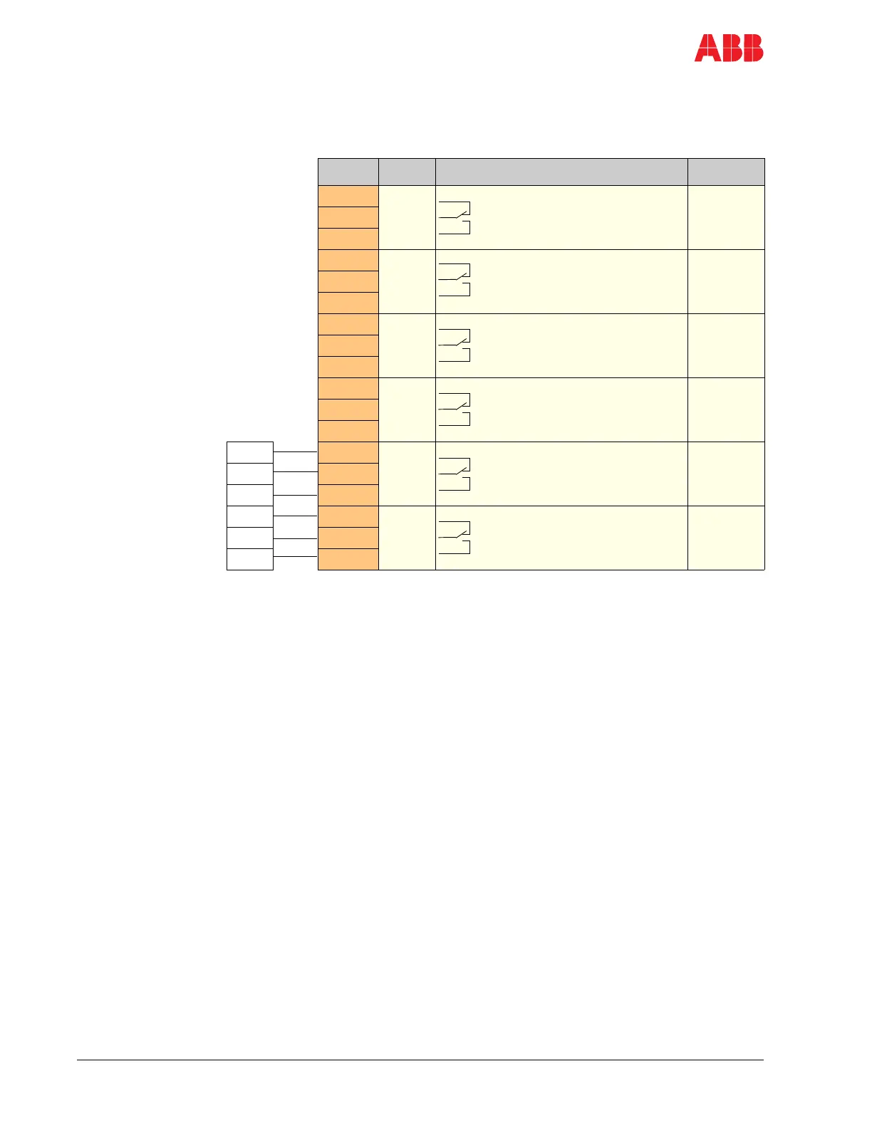
3.3.2.1 IOEC2 (A1541) digital outputs
Table 3-4 Standard digital output signal allocation
Terminal Channel Default setting Par. Group
X21-1
DO01
Ready on
(drive is ready for operation)
X21-2
X21-3
X22-1
DO02
Ready ref
(drive is running)
X22-2
X22-3
X23-1
DO03
Alarm/fault
(alarm is pending)
X23-2
X23-3
X24-1
DO04
Tripped
(drive has shut down)
X10 Terminal
Block *
X24-2
X24-3
X25-1 *
DO05
MV switchgear open command
(low active)
X25-2 *
X25-3 *
X26-1 *
DO06
MV switchgear closed command
(high active)
X26-2 *
X26-3 *
* Factory installed wiring for X10 terminal block. See Appendix G - MV
switchgear guide, located on the CD, for additional MV switchgear
control information.
When the integral input contactor disconnect is installed, X10 is
internal to the drive. Refer to Appendix P.
DC voltage Current
Switching Continuous
24 VDC 8A 6A
48 VDC 1A 6A
120 VDC 0.4A 6A
AC voltage Current
Switching Continuous
24 VAC 8A 6A
48 VAC 8A 6A
120 VAC 8A 6A
230 VAC 8A 6A