■ Control electronics
Inverter control unit
One BCU-0x control unit is required per inverter unit. The type of the control unit depends
on the number of inverter modules as shown below. The control unit is delivered with a
memory unit containing the ACS880 primary control program, optionally with application
programmability. For availability of other control programs, contact your local ABB
representative.
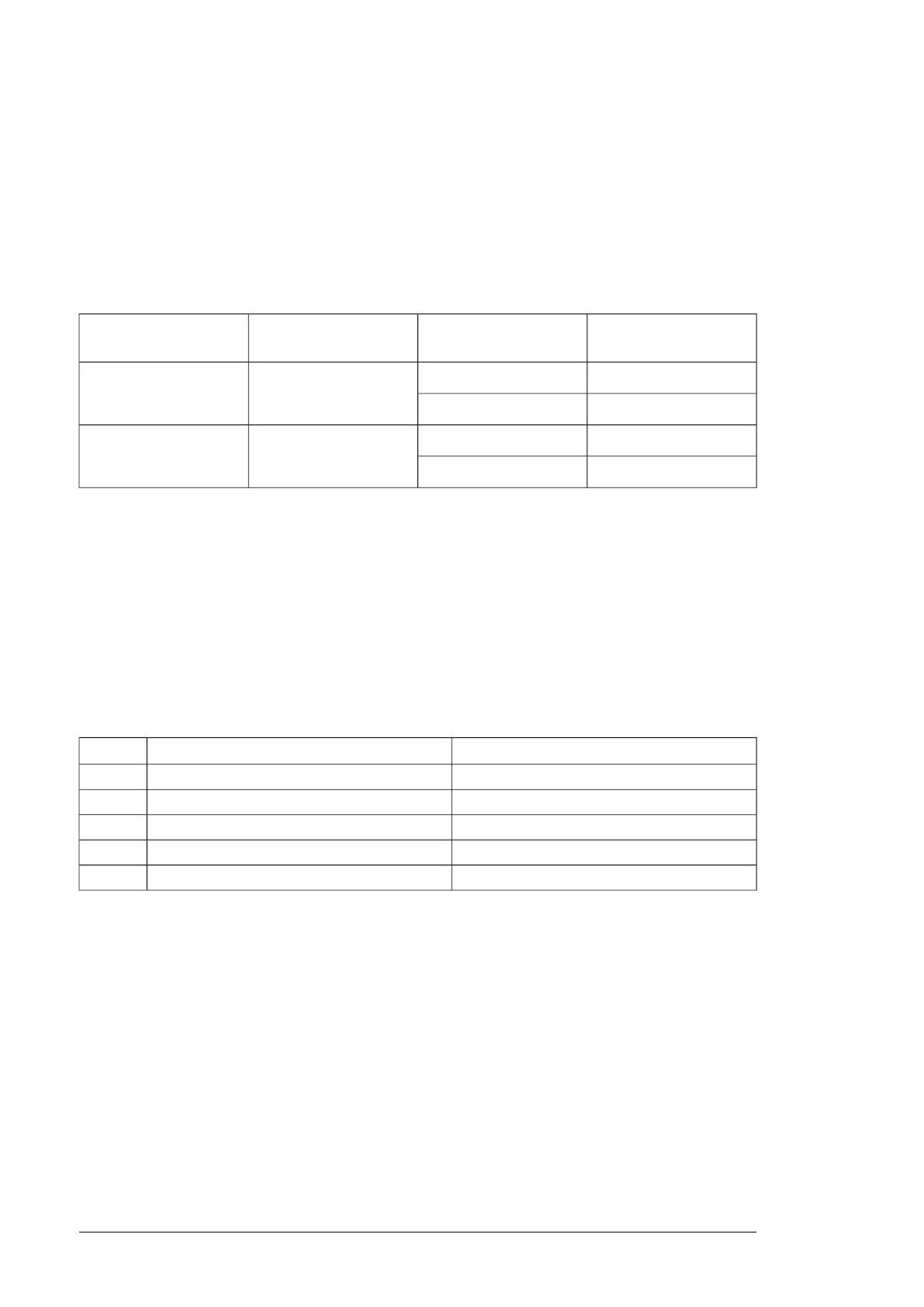
Ordering code
Application programmab-
ility
Control unit typeFrame size
3AXD50000003417No
BCU-02R8i, 2×R8i
3AXD50000011540*Yes
3AXD50000006340No
BCU-123×R8i…6×R8i
3AXD50000011541*Yes
*Application programmability using function blocks based on the IEC 61131-3 standard. For more information, see Programming
manual: Drive application programming (IEC 61131-3) (3AUA0000127808 [English]).
Fiber optic cables
Each frame R8i module is connected to the inverter control unit with a pair of fiber optic
cables.
If the inverter unit is equipped with a DC switch/disconnector, each inverter module is also
connected to the charging controller by a pair of fiber optic cables.
The following kits, each consisting of a pair of plastic fiber optic cables, are available from
ABB:
Ordering codeKit type designationLength
58988821NLWC-022 m
58948233NLWC-033 m
58948250NLWC-055 m
58948268NLWC-077 m
58948276NLWC-1010 m
Control circuit plug connectors
The control circuit plug for connector X50 is not included in the module kit and you must
order it separately.
Note:
Plug connectors for X51, X52 and X53 are included in the module kit.
238 Ordering information

 Loading...


