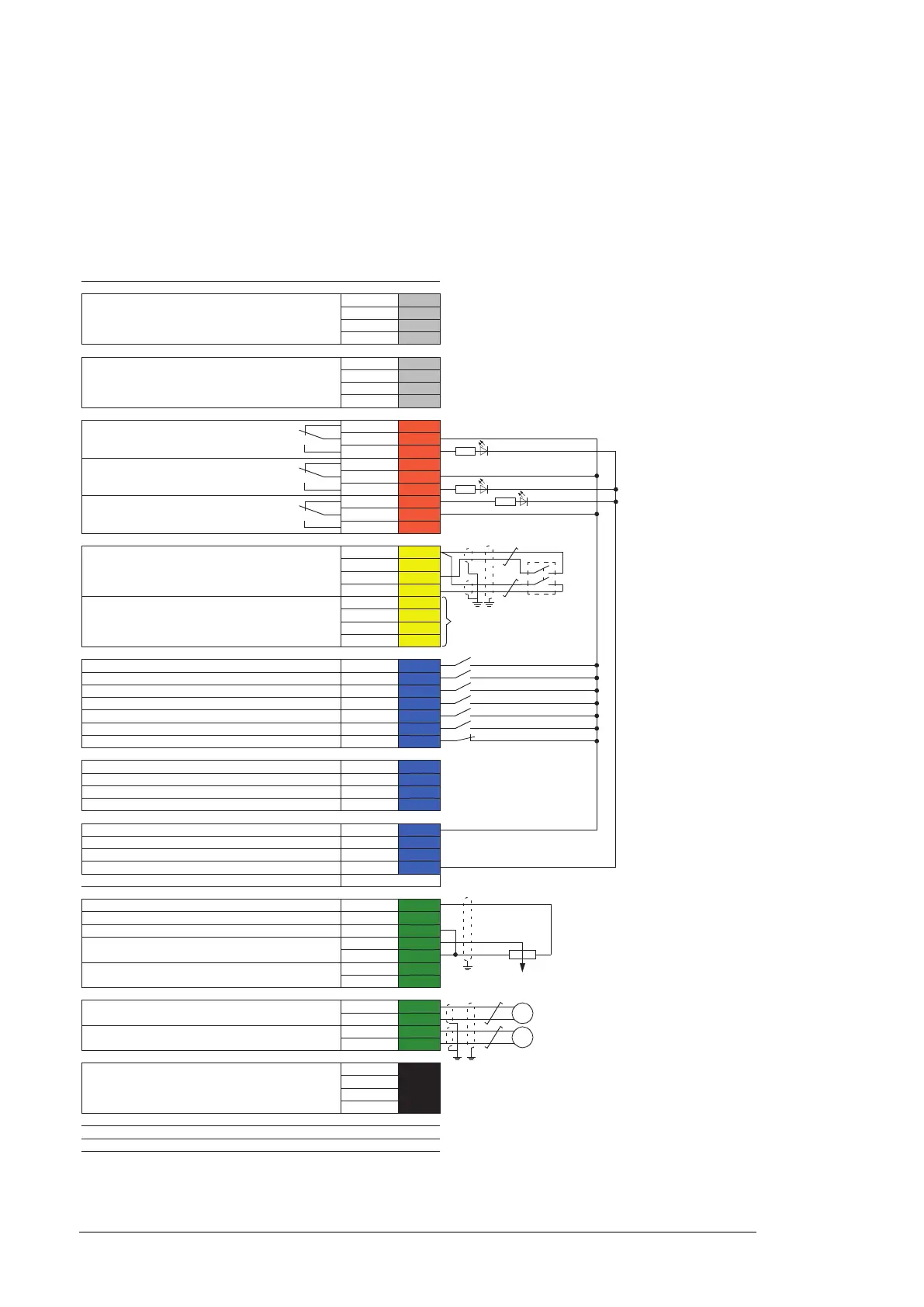
Drive-to-drive link XD2D
Drive-to-drive link
1)
B 1
A
2
BGND
3
Shield
4
RS485 connection X485
Not in use
B
5
A
6
BGND
7
Shield
8
Relay outputs XRO1…XRO3
Ready
250 V AC / 30 V DC
2 A
NC
11
COM
12
NO
13
Running
250 V AC / 30 V DC
2 A
NC
21
COM
22
NO
23
Faulted(-1)
250 V AC / 30 V DC
2 A
NC
31
COM
32
NO
33
Safe torque off XSTO, XSTO OUT
Safe torque off input. Both circuits must be closed for the
drive to start.
2)
OUT 1
SGND
2
IN1
3
IN2
4
Safe torque off output to inverter modules
2)
IN1 5
SGND
6
IN2
7
SGND
8
Digital inputs XDI
Stop (0) / Start (1) DI1
1
Forward (0) / Reverse (1) DI2
2
Reset DI3
3
Acceleration & deceleration select
3)
DI4 4
Constant speed 1 select (1 = on)
4)
DI5 5
By default not in use. DI6
6
Run enable
5)
DIIL 7
Digital input/outputs XDIO
Output: Ready DIO1
1
Output: Running DIO2
2
Digital input/output ground DIOGND
3
Digital input/output ground DIOGND
4
Auxiliary voltage output XD24
+24 V DC 200 mA
6)
+24VD 5
Digital input ground DICOM
6
+24 V DC 200 mA
6)
+24VD 7
Digital input/output ground DIOGND
8
Ground selection switch
7)
DICOM=DIOGND
Analog inputs, reference voltage output AI
10 V DC, R
L
1…10 kohm +VREF 1
-10 V DC, R
L
1…10 kohm -VREF 2
Ground AGND
3
Speed reference
0(2)…10 V, R
in
> 200 kohm
8)
AI1+ 4
AI1-
5
By default not in use.
0(4)…20 mA, R
in
= 100 ohm
9)
AI2+ 6
AI2-
7
Analog outputs AO
Motor speed rpm 0…20 mA, R
L
< 500 ohm
AO1
1
AGND
2
Motor current 0…20 mA, R
L
< 500 ohm
AO2
3
AGND
4
External power input XPOW
24 V DC, 2.05 A
Two supplies can be connected for redundancy.
+24VI
1
GND
2
+24VI
3
GND
4
Safety functions module connection X12
Control panel connection X13
Memory unit connection X205

 Loading...


