Inverter unit control interfaces
■ Overview of control connections of the ZCU control unit
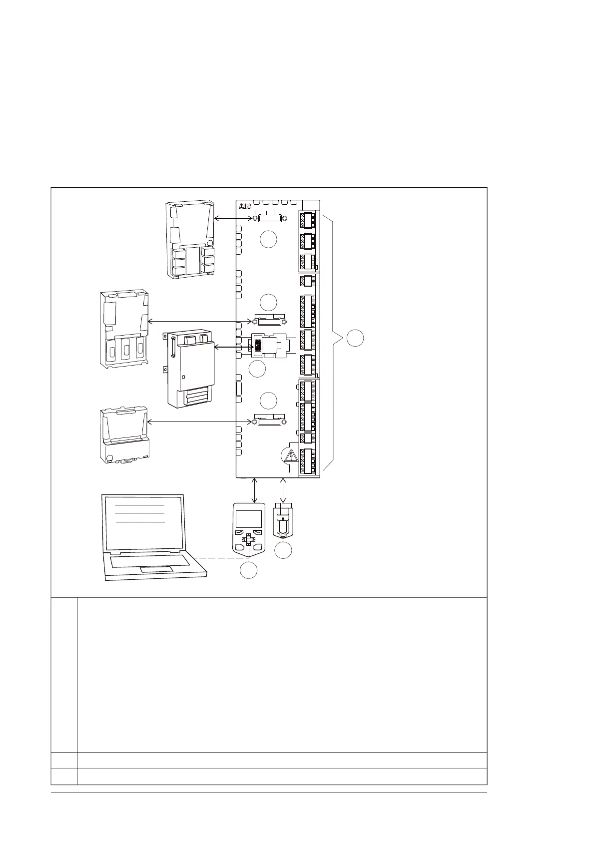
The diagram shows the control connections and interfaces of the ZCU-14 control unit.
It is used with module frame sizes R1i…R7i. Frame R5i modules employ a type ZCU-12
unit which has a different layout but the same connectivity as the ZCU-14.
FXX
FXX
FSO
FXXX
SLOT 1
SLOT 2
SLOT 3
X12
SAFETY
OPTION
X208
FAN2
X210
FAN1
X209
AIR IN
TEMP
X13
CONTROL PANEL
X205
MEMORY UNIT
X
R
O
2
X
R
O
3
X
P
O
W
J1J2
X
A
I
X
A
O
X
D
2
D
X
S
T
O
X
D
I
X
D
I
O
J6
X
D
2
4
X
R
O
1
J3
CLOSE
Option modules can be inserted into slots 1, 2 and 3 as follows:1
SlotsModules
1, 2, 3
Analog and digital I/O extension modules
1, 2, 3Feedback interface modules
1, 2, 3Fieldbus communication modules
2 (X12)FSO-xx safety functions module
When installed into slot 3 of a ZCU-14 control unit, the module will extend over the edge. We recommend you use
slot 1 or 2 instead whenever possible.
2
3
Memory unit.4
Connector for FSO-xx safety functions module (X12). The module reserves slot 2 when connected.5
38 Hardware description

 Loading...


