Start-up
Note:
New brake resistors may be coated with storage grease. As the brake chopper operates
for the first time, the grease burns off and may produce some smoke. Make sure there is
proper ventilation.
Set the following inverter control program parameters (ACS880 primary control program)
in each braking inverter:
•
Disable the overvoltage control (parameter 30.30).
•
Set parameter 31.01 to point to the digital input to which the thermal switch of the brake
resistor is wired.
•
Set parameter 31.02 so that the event generates a fault.
•
Enable the brake chopper by parameter 43.06 Brake chopper enable. If you select
Enabled with thermal model, also set the brake resistor overload protection parameters
43.08 and 43.09 according to the application.
•
Check the value of parameter 43.10 Brake resistance.
• Adjust other brake-related settings as necessary in parameter group 43.
Match the brake chopper operating limits of all braking inverters. You will need to enter
a service-level pass code into parameter 96.02 to access the limit parameters. To obtain
the pass code, contact your local ABB representative.
• Stop all inverters of the drive system (even those not used for braking) if any are
running.
•
Monitor the DC voltage (parameter 01.11) on each braking inverter for a period of
time. Calculate the average of the readings separately for each inverter.
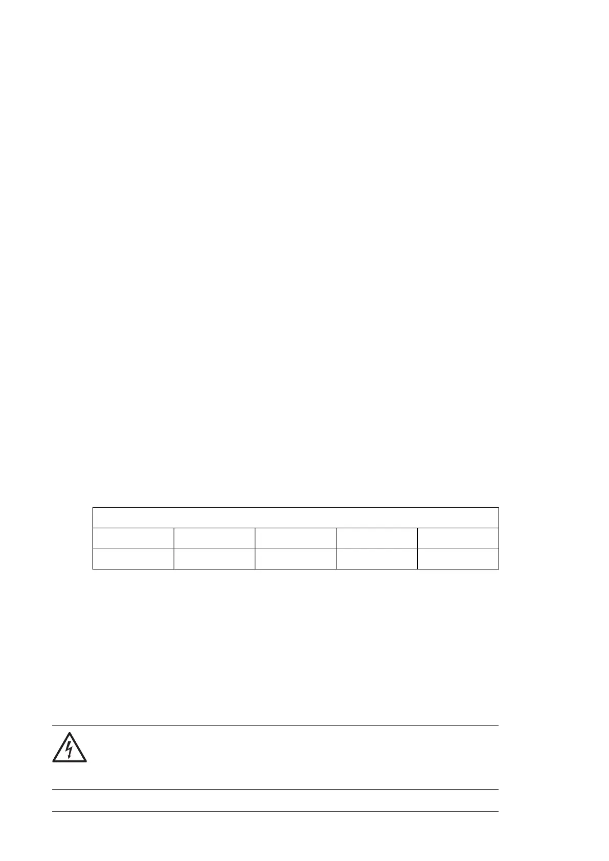
• Select one braking inverter as reference. On this inverter, enter the nominal AC
supply voltage into parameter 95.37. Multiply this value by the number shown in
the table below to get the value of 95.36.
Supply voltage range [V AC] (see parameter 95.01)
500440…480380…415208…240
1.0000.9170.9160.867
[95.36]= [95.37] ×
For example, with a 380…415 V inverter, the value of 95.36 should be 0.916 times
the value of 95.37.
• For each of the remaining braking inverters, divide the average DC voltage value
of the inverter by that of the reference inverter. Multiply the result with the nominal
supply voltage, and enter the result into parameter 95.37. Further multiply the value
of 95.37 by the factor shown in the above table to get the value of 95.36.
•
On all braking inverters, enable custom supply voltage limits using parameter 95.35.
With these parameter settings, a resistor overtemperature situation will trip the inverter
which will then coast to a stop.
WARNING!
Connect the brake resistor to the inverter module before enabling the brake
chopper. On the other hand, if the chopper is disabled, the resistor must be
disconnected.
334 Resistor braking using frames R1i…R4i inverter modules

 Loading...


