Frame R6i and R7i layout
ExplanationItem
30 Operation principle and hardware description
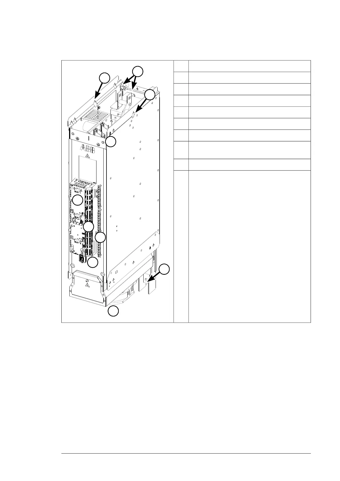
IGBT supply module (frame R6i)
Item Explanation
1 DC (output) connection
2 AC (input) connection
3 ZCU control unit (with slots for optional I/O
modules)
4 I/O terminal blocks
5 Control panel connector, memory unit
6 Grounding/clamping plates for control
cables
7 Cooling fan holder with one fan
8 Lifting eyes
9 The grounding point (PE) between module
frame and cabinet frame
1
2
8
8
6
4
3
5
7
9
DC connection1
AC connection2
ZCU control unit (with slots for optional I/O modules)3
I/O terminal blocks4
Control panel connector, memory unit5
Grounding/clamping plates for control cables6
Cooling fan holder (frame R6i has one fan, R7i has
two)
7
Lifting eyes8
The grounding point (PE) between module frame and
cabinet frame
9
Hardware description 29

 Loading...


