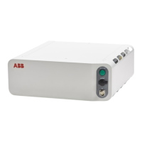
NoteArticle numberSpare part
3HAC051753-003Integr Vision power cable
3HAC051736-003Integr Vision ethernet cable
Required tools and equipment
NoteArticle numberEquipment
Content is defined in section
Standard toolkit for controller on
page 570.
-Standard toolkit
-ESD protective wrist band
Required documents
NoteArticle numberDocument
3HAC059896-009,
3HAC063898-009,
3HAC072448-009
Circuit diagram - OmniCore C30,
Circuit diagram - OmniCore C30
for IRB 14050, Circuit dia-
gram - OmniCore C30 for CRB
15000
3HAC067707-001Application manual - Integrated
Vision
Installing Integrated Vision camera connections
Note/IllustrationAction
DANGER
Before doing any work inside the cabinet,
disconnect the mains power. For more
information, see Electrical safety on
page 31.
1
Location of wrist strap button:
xx1800000683
ELECTROSTATIC DISCHARGE
(ESD)
The unit is sensitive to ESD. Before
handling the unit read the safety inform-
ation in section The unit is sensitive to
ESD on page 47.
2
Fit the cameras to the mounting rail (not
supplied from ABB).
3
Connect the Ethernet cable from the
camera to any of the LAN connectors on
the main computer or the Ethernet
switch.
4
Continues on next page
198 Product manual - OmniCore C30
3HAC060860-001 Revision: P
© Copyright 2019-2022 ABB. All rights reserved.
3 Installation and commissioning
3.8.3 Installing Integrated Vision
Continued

 Loading...