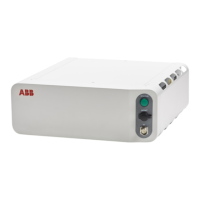
NoteAction
Make sure that the controller power supply is
in run-time mode.
Power on the controller. Check the
indicator LED MS on the power
unit.
2
Wait at least 1 min after power-on.
If the LED MS is:
• Green, proceed with step 8.
• Flashing red/green: a firmware upgrade
error has occurred. This is not supposed
to happen during runtime mode, proceed
with step 12.
• Pulsing red: replace the power unit, step
12.
• Not lit or red: The controller does not
have sufficient DC input voltage. Proceed
with step 3.
Use a multimeter and insulating gloves.Measure the 24 V DC input voltage
to the power unit.
• X5
• X9
3
The input voltage should be 24 V.
Make sure that connectors X5, X9 are connec-
ted properly on both ends.
• If the 24 V DC input voltage is normal,
proceed with step 8.
• If the 24 V DC input voltage is abnormal,
proceed with the next step.
If the connection is OK, proceed with the next
step.
Check connection to the robot sig-
nal exchange proxy.
• A1.X9 (Power unit) - K2.X4
4
If there is a problem with the connection, repair
the connection and go to step 2.
Use a multimeter and insulating gloves.Measure the AC output voltage.
xx1900000043
5
The output voltage should be 230 V/110 V.
Make sure that connectors X6, X7 are connec-
ted properly on both ends.
• If the output voltage is normal,
Troubleshooting the power supply on
page 550, and then Troubleshooting the
robot signal exchange proxy on page 555.
• If the output voltage is abnormal, pro-
ceed with step 6.
Use a multimeter and insulating gloves.Measure the AC input voltage.
• A1.X1 - A1.K1
6
The AC input voltage should be 230 V/110 V.
Make sure that connector X1 is connected
properly on both ends.
• If the input voltage is normal, proceed
with step 12.
• If the input voltage is abnormal, proceed
with the next step.
• If the connection is OK, troubleshoot No
LEDs are lit on the controller on page 502.
• If there is a problem with the connection,
repair the connection and start over.
Check the connection from the
power inlet to the power unit.
7
• If the LEDs are normal, proceed with step
10.
• If the LEDs are abnormal, proceed with
the next step.
Check the LEDs of the Ethernet
ports X3, X12 on the power unit.
8
Continues on next page
Product manual - OmniCore C30 535
3HAC060860-001 Revision: P
© Copyright 2019-2022 ABB. All rights reserved.
6 Troubleshooting
6.3.4 Troubleshooting the power unit
Continued

 Loading...