IEC15000060 V1 EN-US
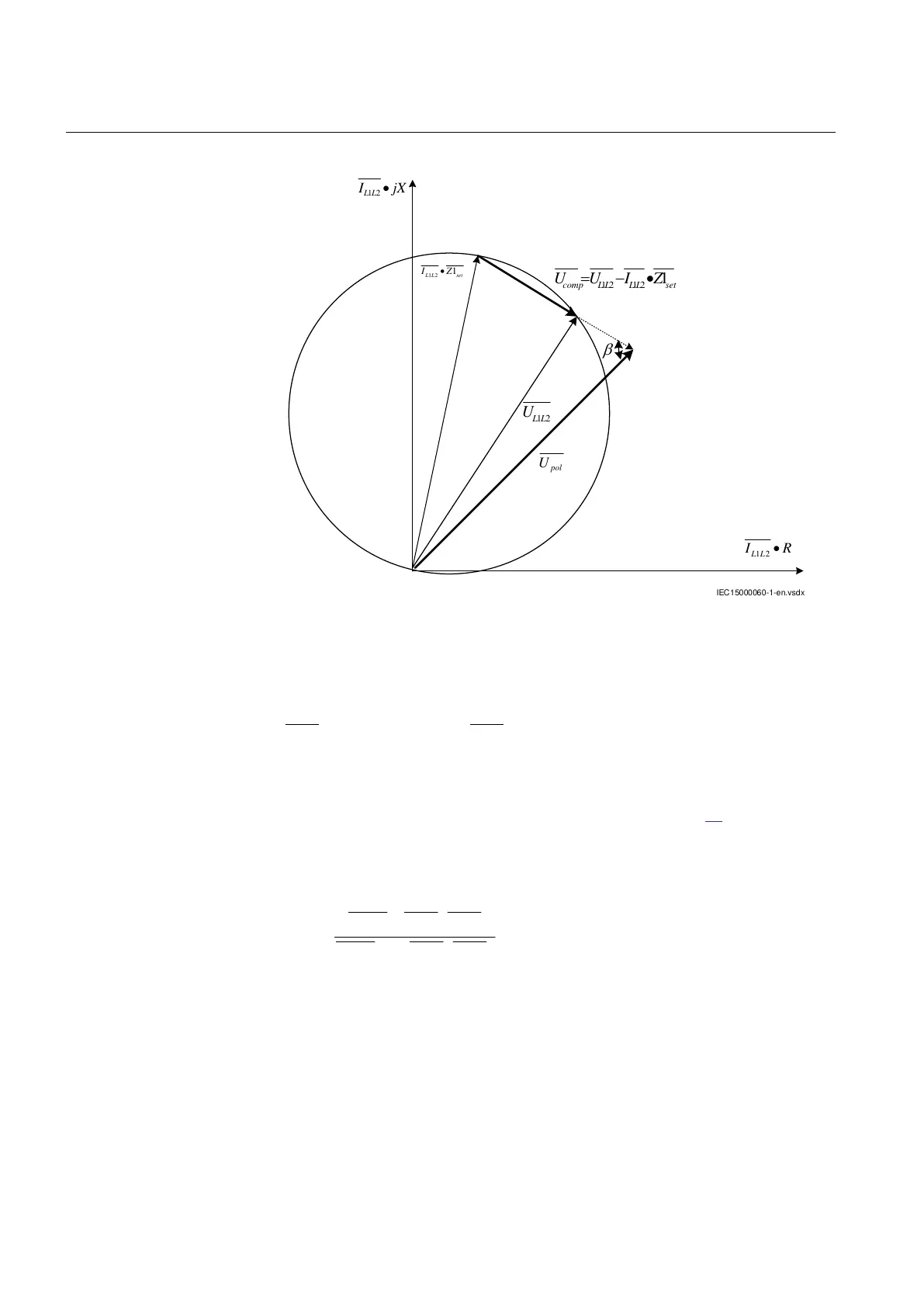
Figure 37: Simplified mho characteristic and vector diagram for phase L1-to-
L2 fault
Offset Mho
GUID-3E13E6D5-0832-4386-9677-9A40BFF42F8F v2
The characteristic for offset mho is a circle with origin as the center and magnitude
of
as the radius, where
is settable through the resistance and reactance
settings.
The condition for operation at phase-to-phase fault is that the angle β between the
two compensated voltages is greater than or equal to 90° (figure
38). The angle will
be 90° for fault location on the boundary of the circle.
The angle β for L1 to L2 fault can be defined according to equation below.
12 12
12 12
1
arg
1
LL LL set
LL LL set
UIZ
UIZ
IECEQUATION15008 V2 EN-US (Equation 6)
Section 6 1MRK 506 382-UEN A
Impedance protection
104 Line distance protection REL650 2.2 IEC
Technical manual