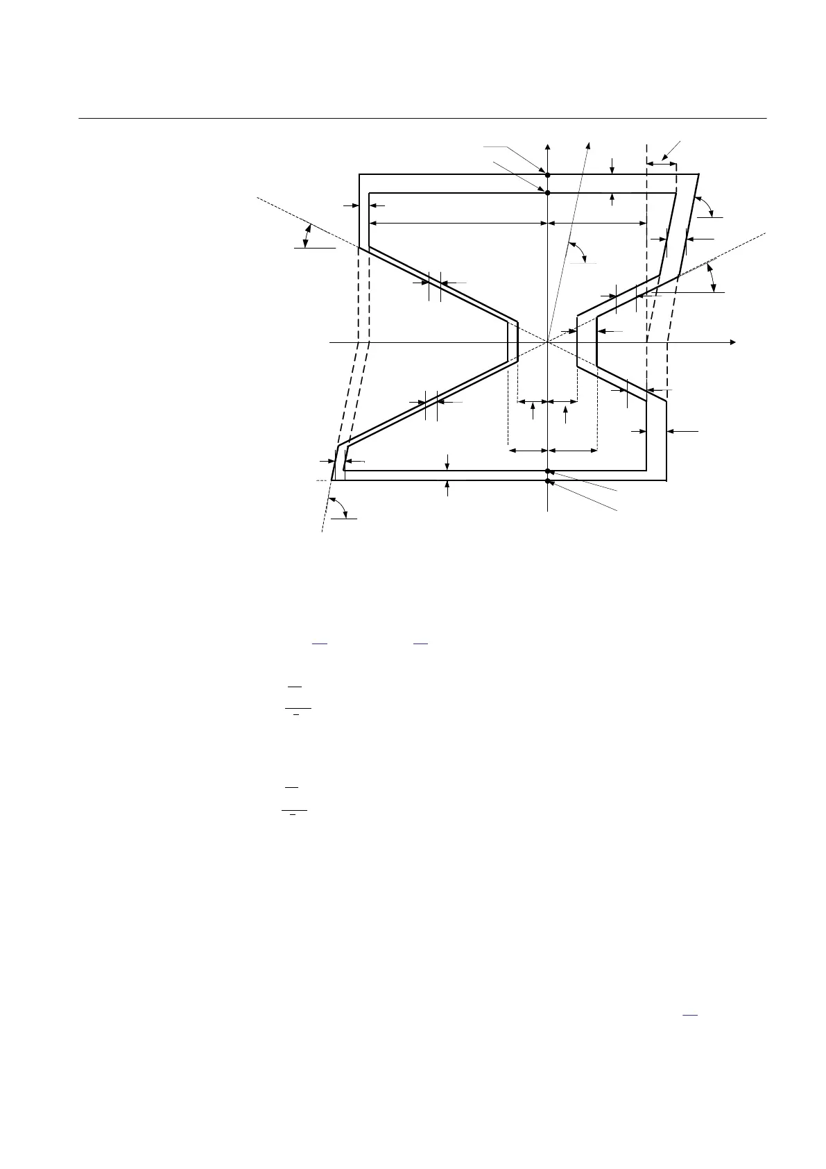
R
jX
ArgLd
ArgLd
RLdOutFw
RLdInFw
R1FInFwR1FInRv
RLdInRv
RLdOutRv
X1InFw
X1OutFw
ZL
R1LIn
X1InRv
X1OutRv
IEC09000222_1_en.vsd
DRv
DRv
DRv
DRv
DRv
DFw
DFw
DFw
DFw
DFw
DFw
j
j
j
IEC09000222 V1 EN-US
Figure 54: Operating characteristic for ZMRPSB function (setting parameters
in italic)
The impedance measurement within ZMRPSB function is performed by solving
equation
10 and equation 11 (n = 1, 2, 3 for each corresponding phase L1, L2 and
L3).
EQUATION1183 V2 EN-US
(Equation 10)
EQUATION1184 V2 EN-US (Equation 11)
The R
set
and X
set
are R and X boundaries.
6.2.6.1 Resistive reach in forward direction
M13877-6 v3
To avoid load encroachment, the resistive reach is limited in forward direction by
setting the parameter RLdOutFw which is the outer resistive load boundary value
while the inner resistive boundary is calculated according to equation 12.
1MRK 506 382-UEN A Section 6
Impedance protection
Line distance protection REL650 2.2 IEC 125
Technical manual