13.7.3.3 Technical data
GUID-0EC4192A-EF03-47C0-AEC1-09B68B411A98 v2
Table 307: Number of INV instances
Logic block
Quantity with cycle time
3 ms 8 ms 100 ms
INV 90 90 240
13.7.4 Loop delay function block LLD
GUID-05D959B5-A55B-437C-8E8F-831A4A357E24 v2
GUID-64B24094-010D-4B8F-8B7B-DDD49499AAE5 v3
The Logic loop delay function block (LLD) function is used to delay the output
signal one execution cycle, that is, the cycle time of the function blocks used.
13.7.4.1 Function block
GUID-EE44CFDF-C8F7-4870-BD1C-98D9CD91FD97 v4
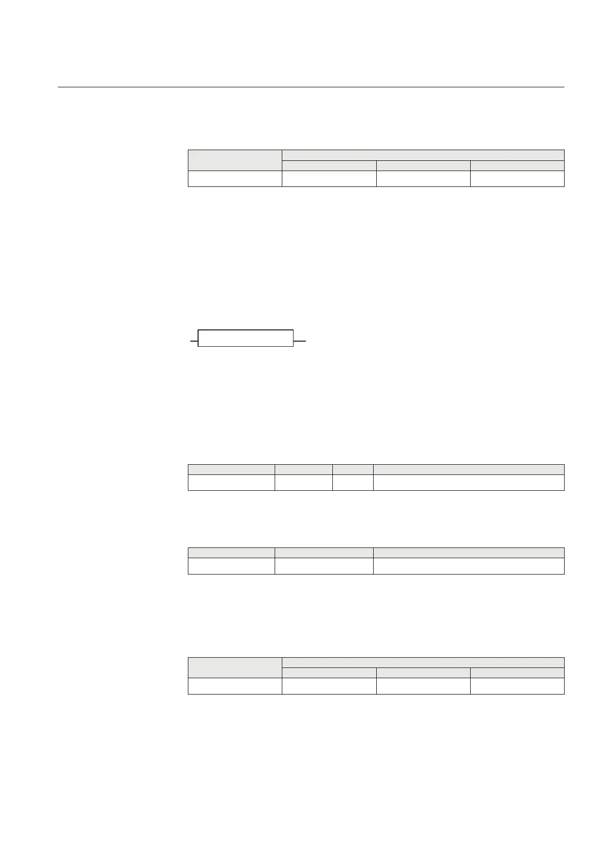
LLD
INPUT OUT
IEC15000144.vsd
IEC15000144 V1 EN-US
Figure 257: LLD function block
13.7.4.2 Signals
PID-3805-INPUTSIGNALS v5
Table 308: LLD Input signals
Name
Type Default Description
INPUT BOOLEAN 0 Input signal
PID-3805-OUTPUTSIGNALS v5
Table 309: LLD Output signals
Name
Type Description
OUT BOOLEAN Output signal delayed one execution cycle
13.7.4.3 Technical data
GUID-B2E6F510-8766-4381-9618-CE02ED71FFB6 v1
Table 310: Number of LLD instances
Logic block
Quantity with cycle time
3 ms 8 ms 100 ms
LLD 10 10 20
1MRK 506 382-UEN A Section 13
Logic
Line distance protection REL650 2.2 IEC 495
Technical manual

 Loading...


