20.2.5.3 Technical data
SEMOD55412-1 v1
M16988-1 v11
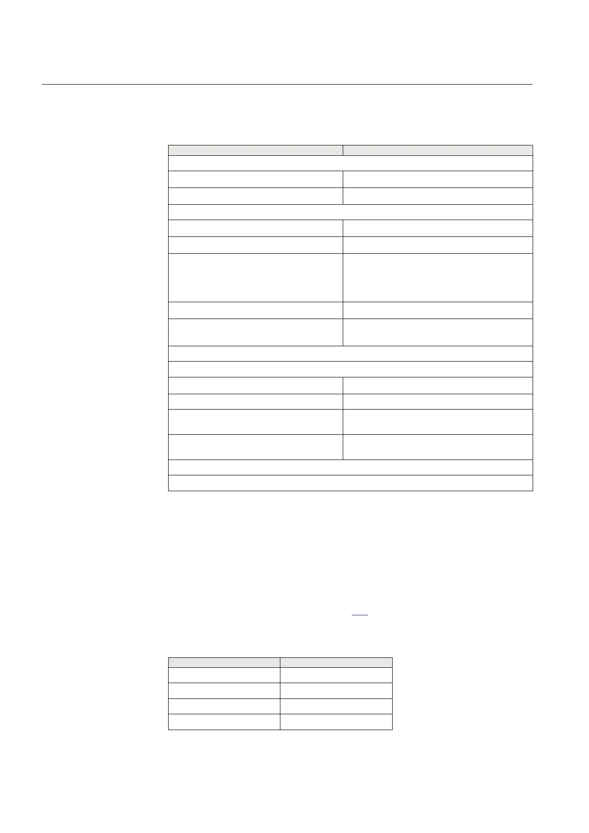
Table 633: TRM - Energizing quantities, rated values and limits for protection transformer
Description
Value
Frequency
Rated frequency f
r
50/60 Hz
Operating range f
r
± 10%
Current inputs
Rated current I
r
1 or 5 A
Operating range (0-100) x I
r
Thermal withstand 100 × I
r
for 1 s *)
30 × I
r
for 10 s
10 × I
r
for 1 min
4 × I
r
continuously
Dynamic withstand
250 × I
r
one half wave
Burden < 20 mVA at I
r
= 1 A
< 150 mVA at I
r
= 5 A
*) max. 350 A for 1 s when COMBITEST test switch is included.
Voltage inputs **)
Rated voltage U
r
110 or 220 V
Operating range 0 - 340 V
Thermal withstand 450 V for 10 s
420 V continuously
Burden < 20 mVA at 110 V
< 80 mVA at 220 V
**) all values for individual voltage inputs
Note! All current and voltage data are specified as RMS values at rated frequency
20.2.6 Analog digital conversion module (ADM)
IP14285-1 v2
20.2.6.1 Introduction
M13664-3 v5
The Analog digital conversion module (ADM) has 12 analog inputs, two PC-MIP
slots and one PMC slot. PC-MIP slots are used for PC-MIP cards, and PMC slot is
used for PMC cards as described in Table 634. The SLM card should always be
mounted on the first ADM module.
Table 634: PC-MIP cards and PMC cards
PC-MIP cards
PMC cards
SR-LDCM SLM
MR-LDCM
IRIG-B
RS485
Section 20 1MRK 506 382-UEN A
IED hardware
838 Line distance protection REL650 2.2 IEC
Technical manual