-3U
0
=U
ref
Operate area
Instrument
transformer
angle error
3I
0
(prim)
3I
0
(to prot)
Characteristic after
angle compensation
RCAcomp
IEC06000651-3-en.vsd
RCADir = 0º
IEC06000651 V3 EN-US
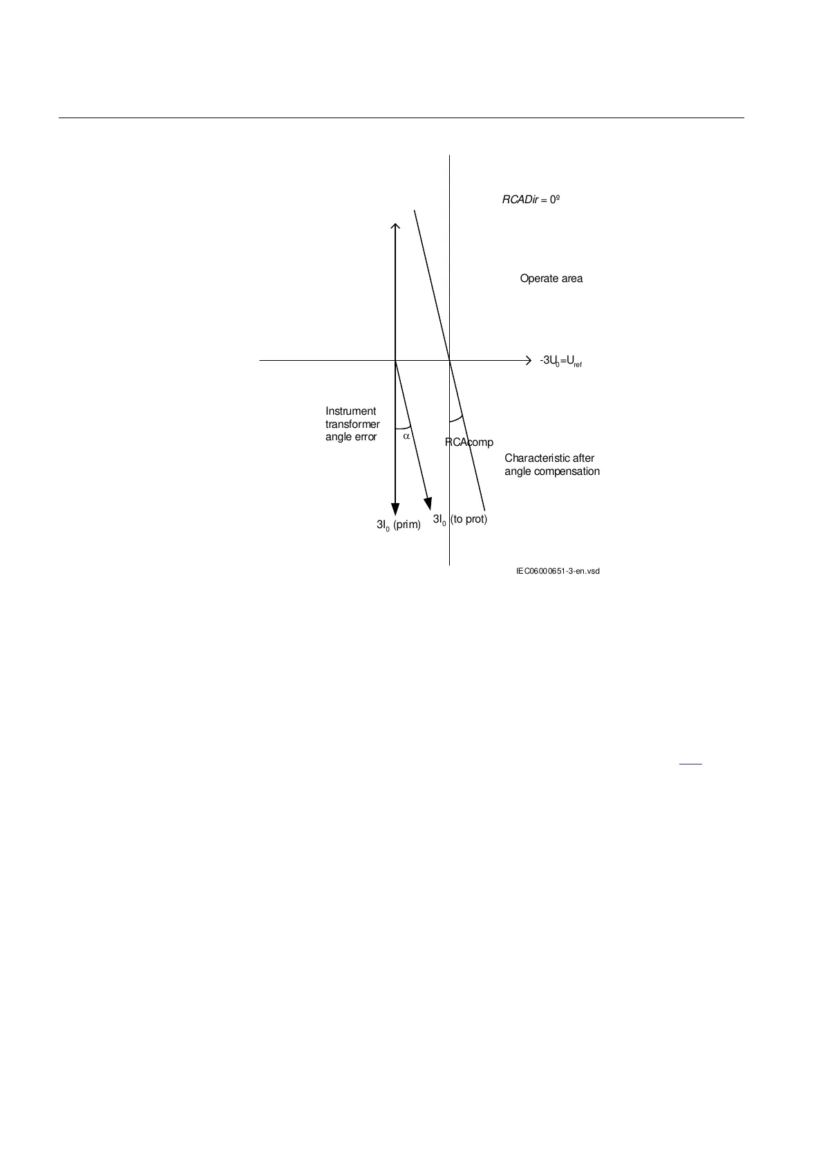
Figure 107: Explanation of RCAComp
Directional residual power protection measuring 3I
0
· 3U
0
· cos φ
SEMOD171963-32 v6
φ is defined as the angle between the residual current 3I
0
and the reference voltage
(U
ref
= -3U
0
e
-jRCA
) compensated with the set characteristic angle RCADir (|
φ=ang(3I
0
)—ang(U
ref
)|). The function operates when 3I
0
· 3U
0
· cos φ gets larger
than the set value SN>. Refer to the simplified logical diagram in Figure
109.
For trip, the residual power 3I
0
· 3U
0
· cos φ, the residual current 3I
0
and the
release voltage 3U
0
, shall be larger than the set levels (SN>, INRel> and UNRel>).
Trip from this function can be blocked from the binary input BLKTRDIR.
When the function picks up, binary output signals START and STDIRIN are
activated. If the output signals START and STDIRIN remain active for the set
delay tDef or after the inverse time delay (setting kSN) the binary output signals
TRIP and TRDIRIN get activated.
The function shall indicate forward/reverse direction to the fault. Reverse direction
is defined as 3I
0
· 3U
0
·cos (φ + 180°) ³ the set value.
Section 7 1MRK 506 382-UEN A
Current protection
226 Line distance protection REL650 2.2 IEC
Technical manual