60 Chapter 3
Main Unit Disassembly Process
IMPORTANT:The outside housing and color may vary from the mass produced model.
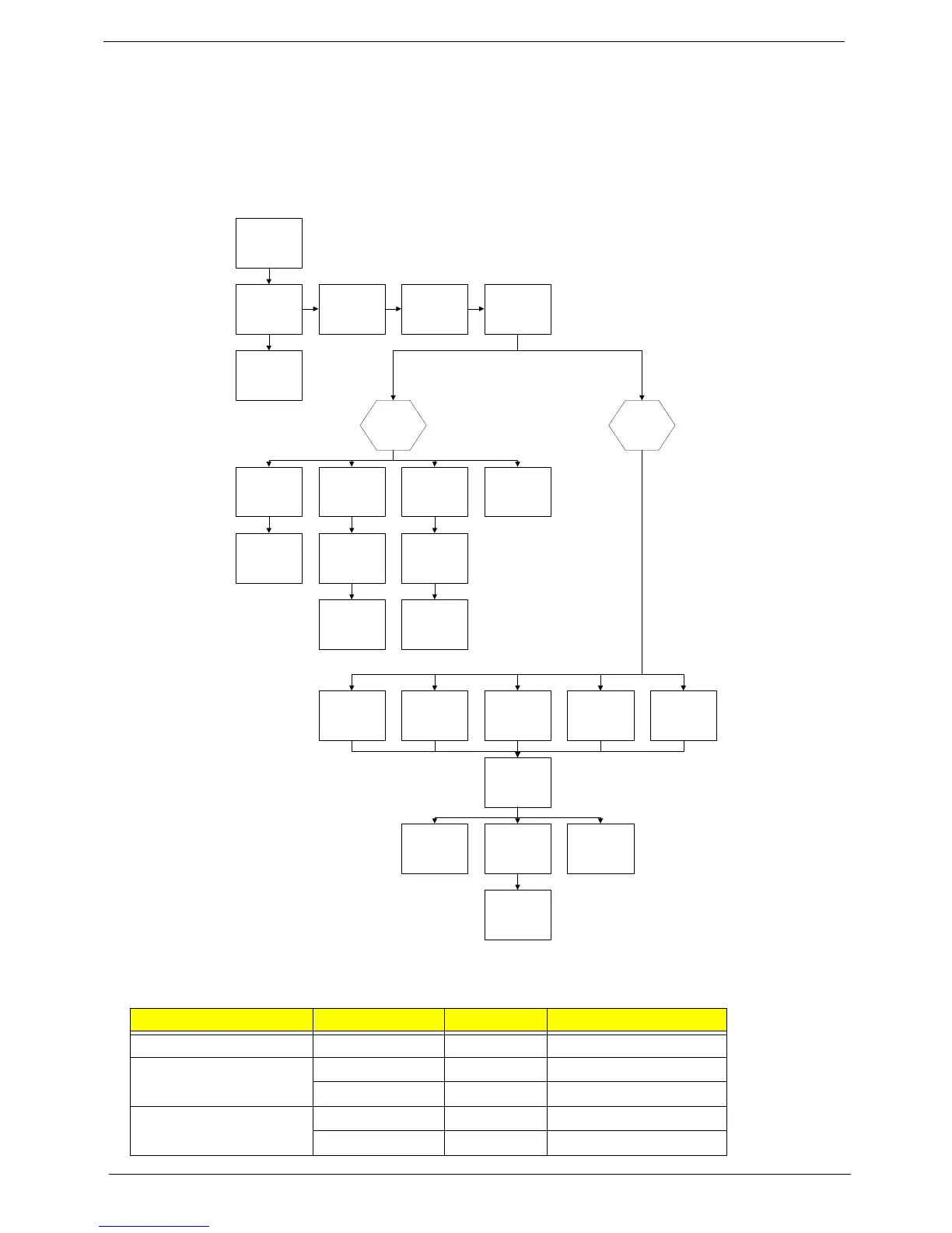
Main Unit Disassembly Flowchart
Screw List
Step Screw Quantity Part No.
Switch Cover M2*3 (NL) 3 86.ATA02.005
LCD Module M2.5*8(NL) 4 86.ATA02.003
M2.5*6 (NL) 2 86.ATA02.002
Upper Cover M2.5*8 (NL) 9 86.ATA02.003
M2.5*4 (NL) 5 86.ATA02.001
Remove
VGA Module
Remove External
Modules before
proceeding
Remove
Thermal Module
Remove
TouchPad
Bracket
Remove
Mainboard
Remove
Switch Board
Remove
Fingerprint
Reader
Remove
Left Speaker
Module
Remove
Switch Cover
Remove
Keyboard
Remove
CPU
Remove
LCD Module
Remove
eKey Board
Remove
Launch Board
Remove
Bluetooth Module
Remove
Subwoofer
Remove
Antenna
Remove
Upper Right
Saddle
Remove
Media Board
Remove
Upper Left
Saddle
Remove
Right Speaker
Module
Remove
TV Board
Remove
USB Board
Remove
Modem Module
Remove
Upper
Cover
Remove
Lower
Cover
Remove
RJ-11 Port