GB 01364
-
Edition 05
- June
08
The
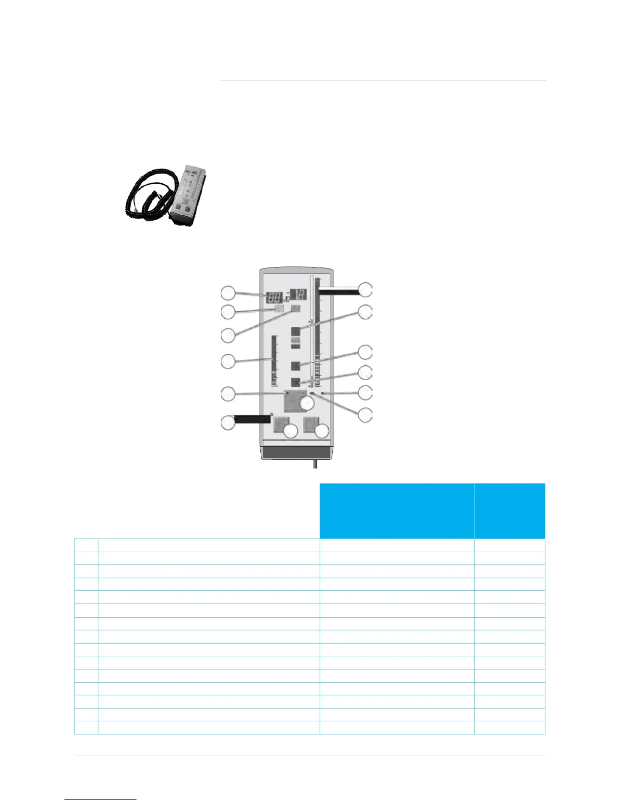
remote control is an
accessory,
but it could be also an option
depending on the helium leak
detector
model.
The remote
control is equipped with a magnet allowing the operator
to place it on a metallic
surface. The
operator can read the helium
signal and has
access
to control
keys such
as cycle command
autocalibration and auto-zero.
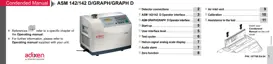
Remote
control
interface
1
2
3
COR
INLET
10
3
ZERO
TEST
10
-2
-3
9
10
-4
10
-5
10
10
-6
10
-7
10
2
HIGH
10
1
4
1
10
-8
10
-9
11
10
-10
10
-1
SNIF
10
-11
12
10
-2
VENT
10
-3
10
-12
mbar
mbar.l/s
5
CYCLE
6
AU TO CA L
ZERO
14
7
8 15
142 range -
182/192
range
ASM 122 D - ASM
1002
Helium Signal digital display
Correction factor COR indicator
Inlet port
pressure
analog display
Test
cycle ON indicator (ON when activated)
6
Cycle Start/Stop control key
Calibration in
progress
indicator
Auto-calibration start control key
Helium signal analogic display
11
Sniffing
test
mode ON indicator
Helium signal standard scale ON indicator
Helium signal Zero scale ON indicator
(1) If the
pressure measurement
kit is installed