Controlling the detector with the
I/O
inter
face
Purpose of the
I/O
inter
face
Location of the
I/O
inter
face
The
I/O interface
makes
it possible to control the leak
detector
with
a
PLC
or any other external control device.
The
I/O interface is available on a Sub D. 25 pin
Female
connector
located on the back of the leak detector.
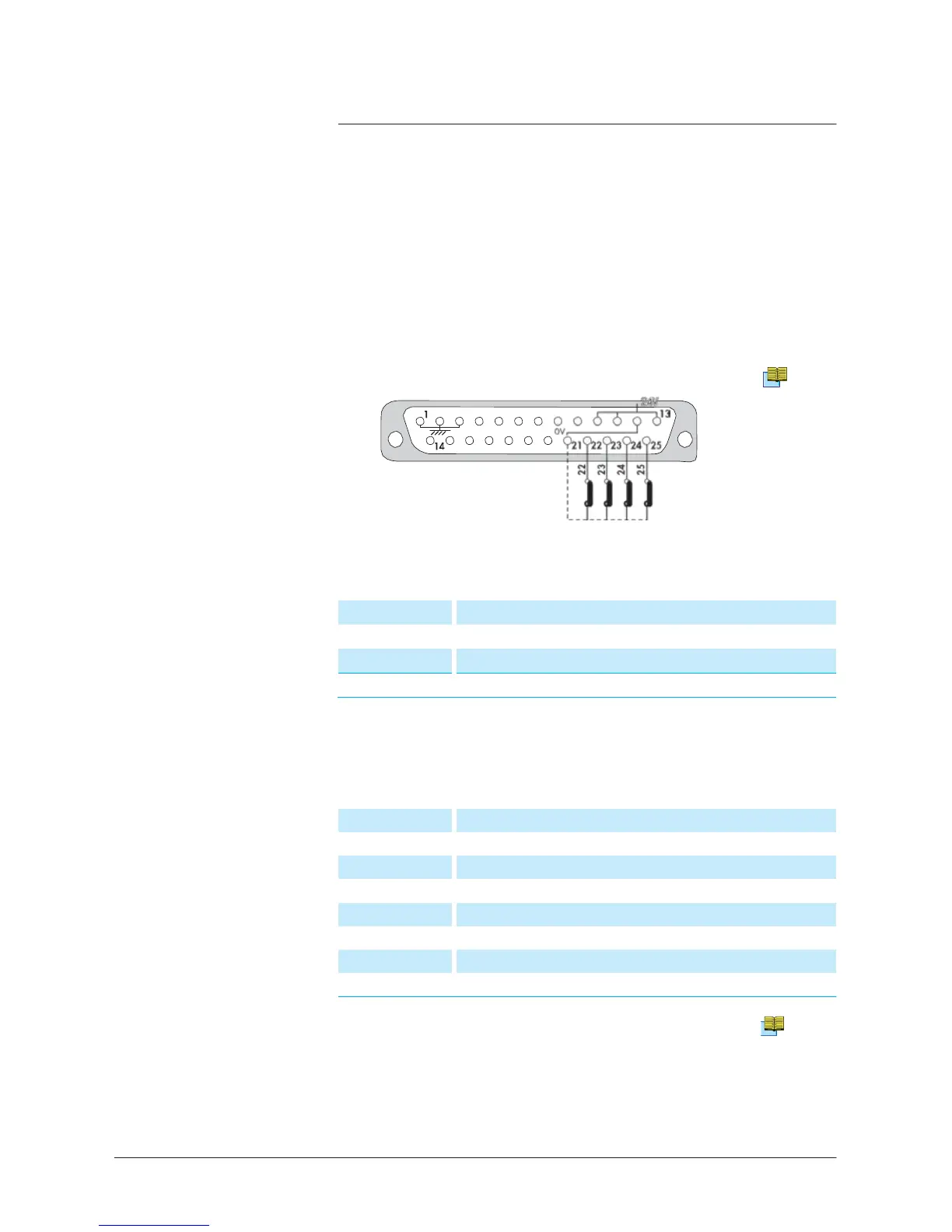
Prepare the
connector wiring
(Sub D.
25
pin
male
connector)
The common
points of
the
controls
are pins
12
and
21.
B
210
It is
recommended
to
use
a shielded cable which is grounded on the
connector
cap.
The
controls
(inputs)
The
signals
(outputs)
Dry contacts:
Direct current: 60 V
-
60 W or 2 A max
Alternative current: 40 V
-
125 VA or 2 A max
Closed contact:
4
-
17
Sniffer
mode
(LDS)
6
-
19
Detector
ready to
test.
Good part
(P
ASS)
5
-
18
Defect
7
-
20
Cycle start
8
-
9
Detector
ready to
test.
Bad part
(F
AIL)
2 -15
Analog
output
0
-
10
VDC corrected Exponent Helium
s
i
g
n
al
1
-
14
0
-
8 VDC tracer gas analogic output
3
-
16 Corrected
Mantissa
Helium signal
Nota
:
1
-
2
-
3 = internal ground
12 =
common (external
ground)
21 =
common (external
ground)
300
1/2