Analog outputs
G
300
1.00E+00
1.00E-01
He signal
This
curve gives directly the
correspondance
between the output
voltage and the signal for all leak
detectors
except ASM 142
S
and ASM 102 S.
For
these
products, it is
necessary
to correct the curve He signal.
ASM 142 S: He signal = curve He signal x
15
0 - 10 Volt
The
purpose of the
present
chapter is to
present
the logarithmic response
of this output.
To
get directly the
corrected
helium signal as it is displayed on the
Digital display,
use
the 0 - 10 Volt linear output (refer to
B
300
)
on
the
same
I/O
interface
connector.
Note: the
pressure
analog output is not the
same
as the
helium
output.
1.00E-02
1.00E-03
ASM 102 S: He signal = curve He signal x
1000
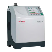
Example: V = 4.96 V
-
All leak
detectors
except
ASM
142
S
and
ASM
102
S
9.1
x
10
-
6
m
bar
.
l
/
s
-
ASM 142
S
9.1x10
-6
x 15
1.365x10
-4
mbar
.l/s
-
ASM 102
S
9.1x10
-6
x 1000
9.1x10
-2
mbar
.l/s
Pressure P
(mbar)
Voltage V (volt)
P
=
10
(U-5,5)
mbar
0 - 8 Volt
Reminder:
n
The
0
-
8 Volt logarithmic output is located on the I/O interface
connector:
Pin
1
Pin
14
-
ASM
182/192
family, ASM 1002: signal
connected (COEF.SENS
and
COEF.MODE
applied)
-
ASM 142 family, ASM 122 D, ASM 102 S, ASI 22: signal not
corrected.
n
This
output
corresponds
to the
electronic
signal obtained with the best
sensitivity
mode of the leak detector.
n
This
output
corresponds
to the
electronic
signal obtained at the level
of the analyzer cell
(VHS
amplification
system)
and
does
not
include
the
correction
factors
generated
by the internal and external calibration.
n
The
chart and
curve shows
the
correspondance between
output voltage
and
helium
signal.
The
helium signal given by the
present
chart needs
to be multiplied by
COEF.SENS
which is adjusted during the internal
(auto)calibration: refer to Calibration or Configuration
menus
(see
Chapter C) in order to get
access
to
COEF SENS
value.
This
COE
F
.SENS
value is modified at each autocalibration: its
takes
into account the fact
that the
characteristics
of the leak
detector
(analyzer cell and pumps
status)
and
evoluates
as it is used.
n
If an external
correction
ratio like
VAC COR, SNIF COR
or
GL COR
is
activated, the helium signal given by the
present
chart also
needs
to be
multiplied by this ratio: refer
C
300.
1/2
1.00E-04
1.00E-05
1.00E-06
1.00E-07
1.00E-08
1.00E-09
1.00E-10
1.00E-11
1.00E-12
1.00E-13
0 1