Setting and
maintenance
part
presentation
of the control panel
GB 00966 -
Edition
06 -
June
08
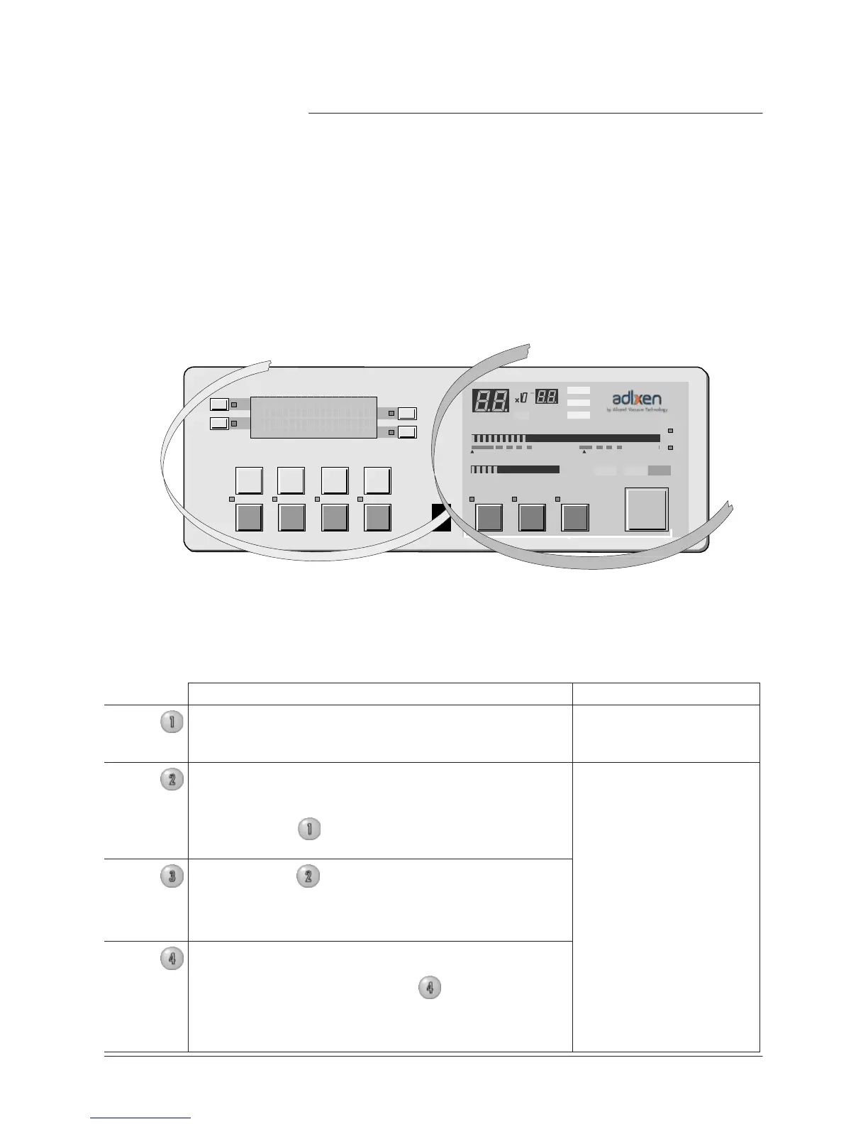
The
control panel can be divided into two different sections.
•
The section
located on the right of the control panel is dedicated to
the user.
•
The section
located on the left of the control panel dedicated to the
setting
and
maintenance (adjustments, functions, menu access,
etc.).
Operation
par
t
F1
F2
LEAK
RA
TE
F3
COR
mbar
.l/
s
Pa.m
3
/s
T
orr
.l/
s
F4
10
-12
10
-11
10
-10
10
-9
10
-8
10
-7
10
-6
10
-5
10
-4
10
-3
10
-2
10
-3
10
-2
10
-1
1
10
1
10
2
10
3
mbar
hPa
T
orr
STDBY
EVAC TEST
NEXT
-
+
RESET
INLET PRESSURE
SET
POINTS
SPECTRO
MAINTENANCE
OTHER
AUTO CAL
SNIFFER
ZERO
CYCLE
Setting
and
maintenance
par
t
Levels
Description
•
The detector
offers 4 user interface
levels
for this
section
to
accomodate any application requirements.
Setting
and
maintenance
part
Level
1
This
level has very limited information on the
alphanumeric display
(LCD). This
level is generally
selected
for production types of applications.
No
access
to control keys
(Cycle key included)
Level
2
This
level allows the operator to visualize some
parameters
without the possibility of making any
changes.
Same
as Level
1
, this level is
usually selected
for
production types of applications.
Access
to all the control
keys
Same
as level
2
but with possibility to
set
some
parameters.
This
level is generally
selected
for maintenance
Level
4
This
level allows
access
to all the
parameters
and is
generally
used
for
settings
all the parameters.
Note: When switching from level
4
to any other
level, the switch can be performed without using the
password.
This
level is generally
selected
for
R&D
applications.