Total radiation dose 6600 cGy·cm
2
0 cm0 cm
200 cm200 cm
11
22
3
4
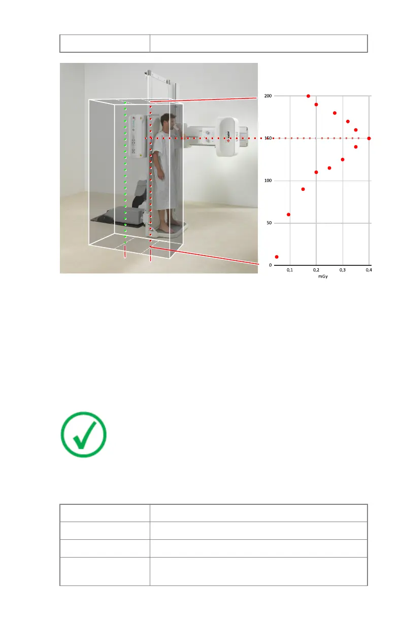
1.
Vertical axis indicating operator position at the right side of the table (at
15 cm from the right side of the tabletop and at 50 cm distance from
central X-ray beam) and height range of stray radiation measurement (0
cm - 200 cm)
2.
Vertical axis indicating operator position at the left side of the table
3.
Horizontal axis indicating the position of the X-ray tube
4.
Stray radiation in mGy measured at the operator position [1]
Figure 54: Significant zone of occupancy and stray radiation during
examination with vertical table
Note: The stray radiation will be significantly lower at a position
at the left side of the tabletop (indicated with number [2] in the
illustration). The operator should take this position during the
exposure, and still be able to give assistance to the patient.
Table 4: Conditions for measuring stray radiation values represented in the
illustrations
Workflow Fluoroscopy
Object PMMA phantom measuring 25 x 25 x 25 cm3
Collimation 10 cm x 10 cm
Exposure parameters 125 kV, 80 mA, 10 frames per second, 10 ms pulse
width
DR 800 | Introduction | 75
0392C EN 20210309 1049