562 Chapter11
Synthesizer Section
Unlocked Fractional N PLL
4. Check the frequency at A14TP1. It should equal the value found by
pressing
CAL, MORE 1 OF 2, FREQ DIAGNOSE, and RAW OSC FREQ.
5. Check the tune voltage at R240 in function block AQ.
6. Look up the expected problem area in Table 11-9 on page 562 with
the information from steps 4 and 5. Go to the appropriate
troubleshooting steps.
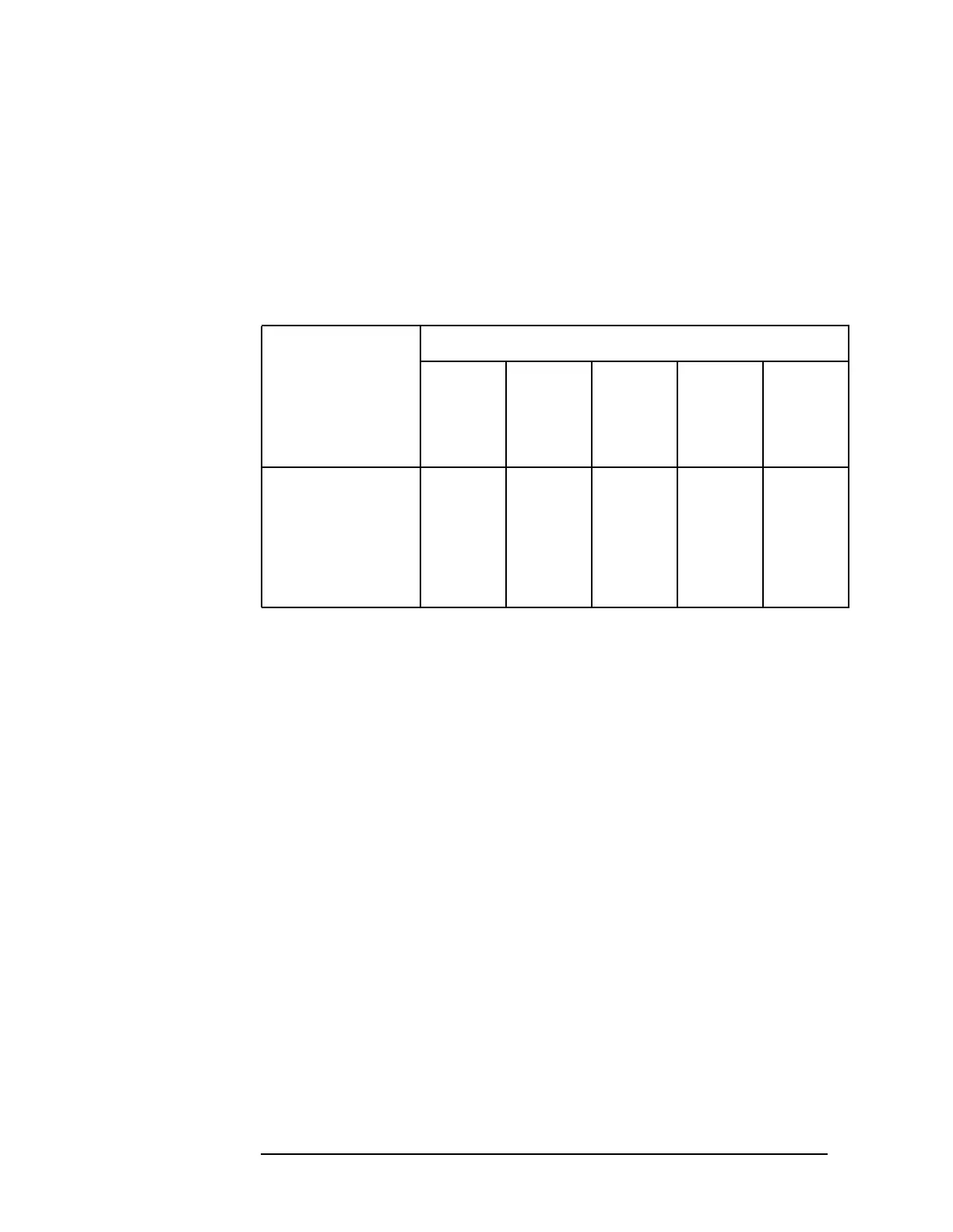
Table 11-9UnlockedFractionalNTroubleshootingAreas
Measured VCO
Frequency
Relative to
Expected Value
Tune Voltage
Below −4
V
About
−3.3 V
Between
−2 V and
+10 V
About
+11 V
Above
+12.5 V
Measured > expected VCO
clamp
VCO Divideror
integrator
Divideror
integrator
VCO
clamp
Measured < expected VCO
clamp
Divideror
integrator
Divideror
integrator
VCO VCO
clamp
Measured, not
oscillating
VCO
clamp
VCO VCO VCO VCO
clamp
7. VCO clamp troubleshooting: Q131, Q132 and the associated
components should limit the tune voltage at R240 to about −3.3 V to
+11V.Iftheintegrator(itsoutputvoltageis
on TP13) tries to produce a voltage outside this range, excess current
is shunted through CR131 and Q131 for positive excursions or
CR132 and Q132 for negative excursions. The base of Q131 should
be at about +9.60 V, and the base of Q132 should be at about −2.09 V
for proper operation.
8. VCO troubleshooting: Check the dc biases in the VCO function block.
The bias voltages, for some points in the VCO, are indicated in
Figure 11-8 on page 564
 Loading...


