aurora
Sonata
Hand Held ISDN Tester—User Guide
1-16 427869
Your aurora
Sonata
comes ready fitted with the interface modules
that your organisation has chosen. For details about other
interfaces see Chapter 9 section 2, or contact your Agilent
Technologies representative.
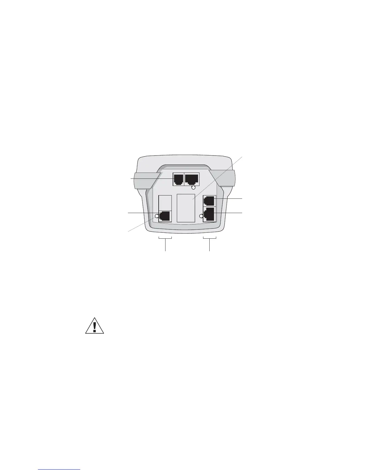
The interface connectors panel
The diagram below shows a typical aurora
Sonata
connectors
panel, fitted with a set of Basic Rate connectors. It may not
exactly match the interfaces fitted on your particular tester, or
the way they are arranged.
LED
Line Connector
Primary Rate
Connectors
Clock Input
Connector
Line
Connector
Blanking
Plate
'U' Interface 'S' Interface
Each interface has an LED which shows green (Monitor
mode) or red (Simulate mode) when the interface is selected.
Where two interfaces are in use (e.g. when monitoring on the
U interface), the LEDs on both interfaces light up.
Warning: Interface modules
Do not remove an interface module unless you have been
specifically authorised by Agilent Technologies to do so.
Connector safety
The connectors on aurora
Sonata
conform to EN60950 safety
status classifications as shown in the table overleaf.
Connection with other equipment should be made such that
the equipment continues to comply with clause 2.3 of
EN60950 for SELV circuits, and with the requirements of
clause 6 for TNV circuits after a connection is made.

 Loading...


