Publication 1756-UM050A-EN-P - December 2001
2-8 Installing the 1756-ENBT Module
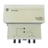
Applying Chassis Power
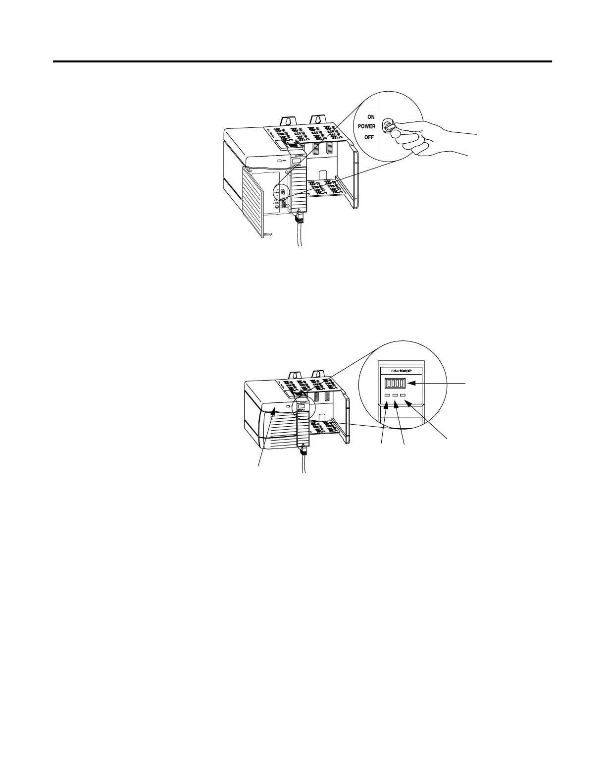
Checking Power Supply
and Module Status
Check the LED indicators and alphanumeric display to determine if
the power supply and module are operating properly.
The alphanumeric display should cycle through the following states:
“TEST - PASS - OK - REV x.x,” where “x.x” is the module’s firmware
revision. The display then alternates between “OK” and the module’s
default BOOTP address.
If the alphanumeric display and LED indicators do not produce the
expected states refer to Appendix A for help in troubleshooting your
module.
What’s Next?
The following chapter describes some Ethernet basics you should
know before configuring your module.
31280-M
31281-M
LINK NET OK
OK indicator is
Power Supply
LINK
NET
red during self-test,
then green.
Alphanumeric
Indicator is GREEN
Display

 Loading...