Publication 1756-UM050A-EN-P - December 2001
8-2 Interfacing with FLEX I/O
Set Up the Hardware
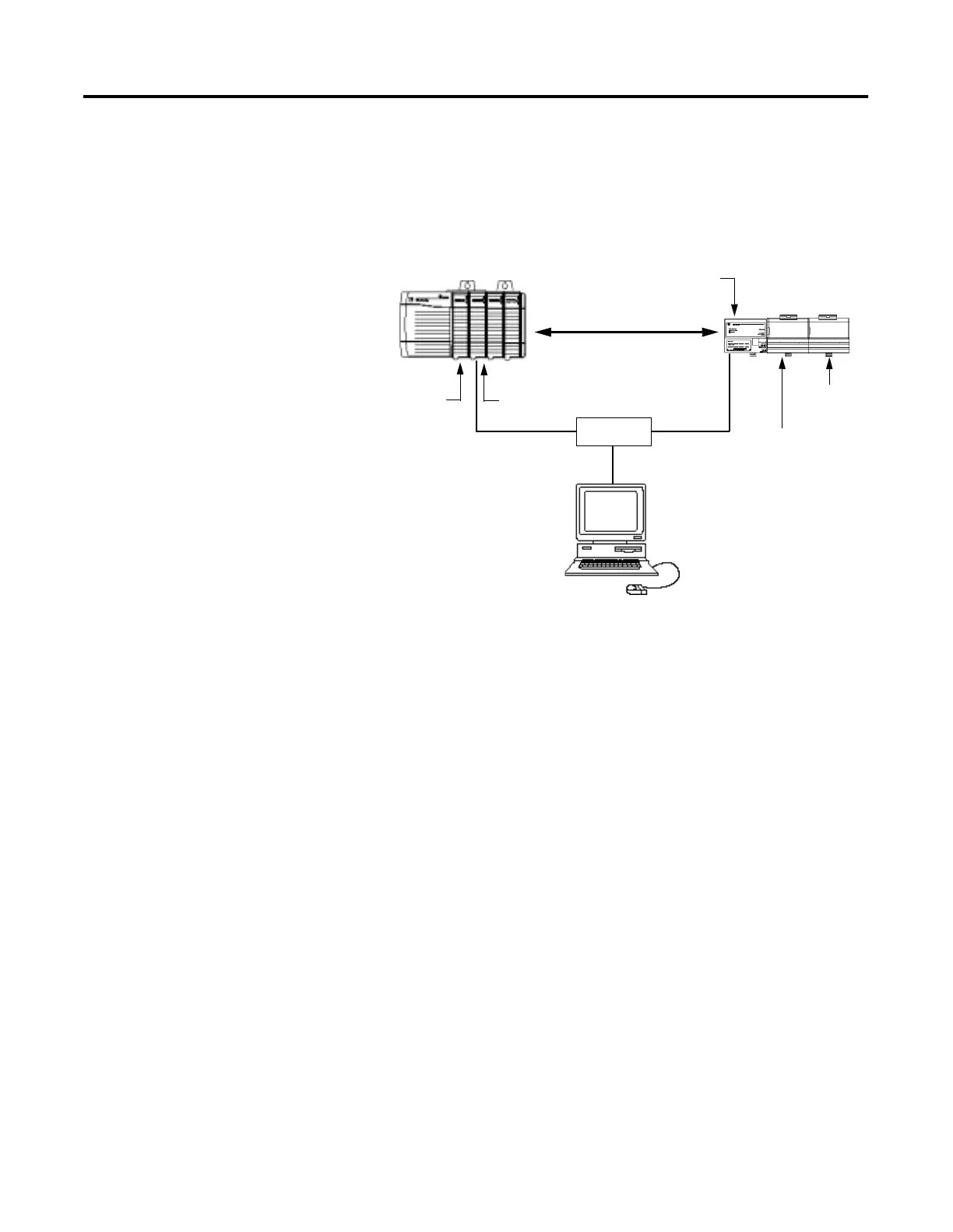
In this example, the ControlLogix chassis contains the Logix 5550
processor in slot 0 and a 1756-ENBT bridge module in slot 1. The
1794-AENT adapter is mounted on a DIN rail with a 1794-IB16 digital
input module and 1794-OB16 digital output module. You will also
need a power supply (not shown) for the FLEX I/O.
To work along with this example set up your system as shown above.
• Note that in the example application, the Logix5550 controller
and 1756-ENBT module are assumed to be in the slots shown
above.
• Verify the IP addresses for your programming terminal,
1756-ENBT module, and 1794-AENT adapter.
• Verify the position (slot) of the I/O modules on the DIN rail.
• Verify that all wiring and cabling is properly connected.
• Make sure your communication driver (e.g., AB_ETH-1) is
configured in RSLinx as described in Appendix C.
Slot 0 1
Programming
130.130.130.1
Terminal
Local
Chassis
FLEX I/O
Slot 0 1
Logix5550
Controller
1794-OB16
Digital Output
1794-IB16
Digital Input
1756-ENBT
130.130.130.2
1794-AENT
130.130.130.3
Data
Switch

 Loading...