IE340 Series Installation Guide
44
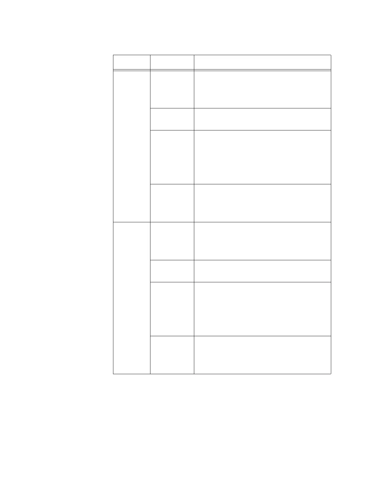
PWR1 Off The switch is not receiving power on the
PWR 1 connector or the input power from
the DC power supply is outside the normal
operating range of the unit.
Solid Green The switch is receiving power on the PWR 1
connector and is operating normally.
Solid Yellow The switch is receiving power on the PWR1
connector, but the power is under the
minimum voltage. The minimum voltage
depends upon the operating mode of non-
Poe, Poe, or PoE+. Refer to Table 9 on
page 51.
Solid Red The switch is receiving power on the PWR1
connector, but the power exceeds the
maximum voltage. The maximum voltage
depends upon the operating mode.
PWR2 Off The switch is not receiving power on the
PWR 2 connector or the input power from
the DC power supply is outside the normal
operating range of the unit.
Solid Green The switch is receiving power on the PWR 2
connector and is operating normally.
Solid Yellow The switch is receiving power on the PWR2
connector, but the power is under the
minimum voltage. The minimum voltage
depends upon the operating mode of non-
Poe, Poe, or PoE+. Refer to Table 9 on
page 51.
Solid Red The switch is receiving power on the PWR2
connector, but the power exceeds the
maximum voltage. The maximum voltage
depends upon the operating mode.
Table 4. Status LEDs (Continued)
LED State Description

 Loading...


