Transport, siting and installation
70
Transport, siting and installation
0000010038-003- GB
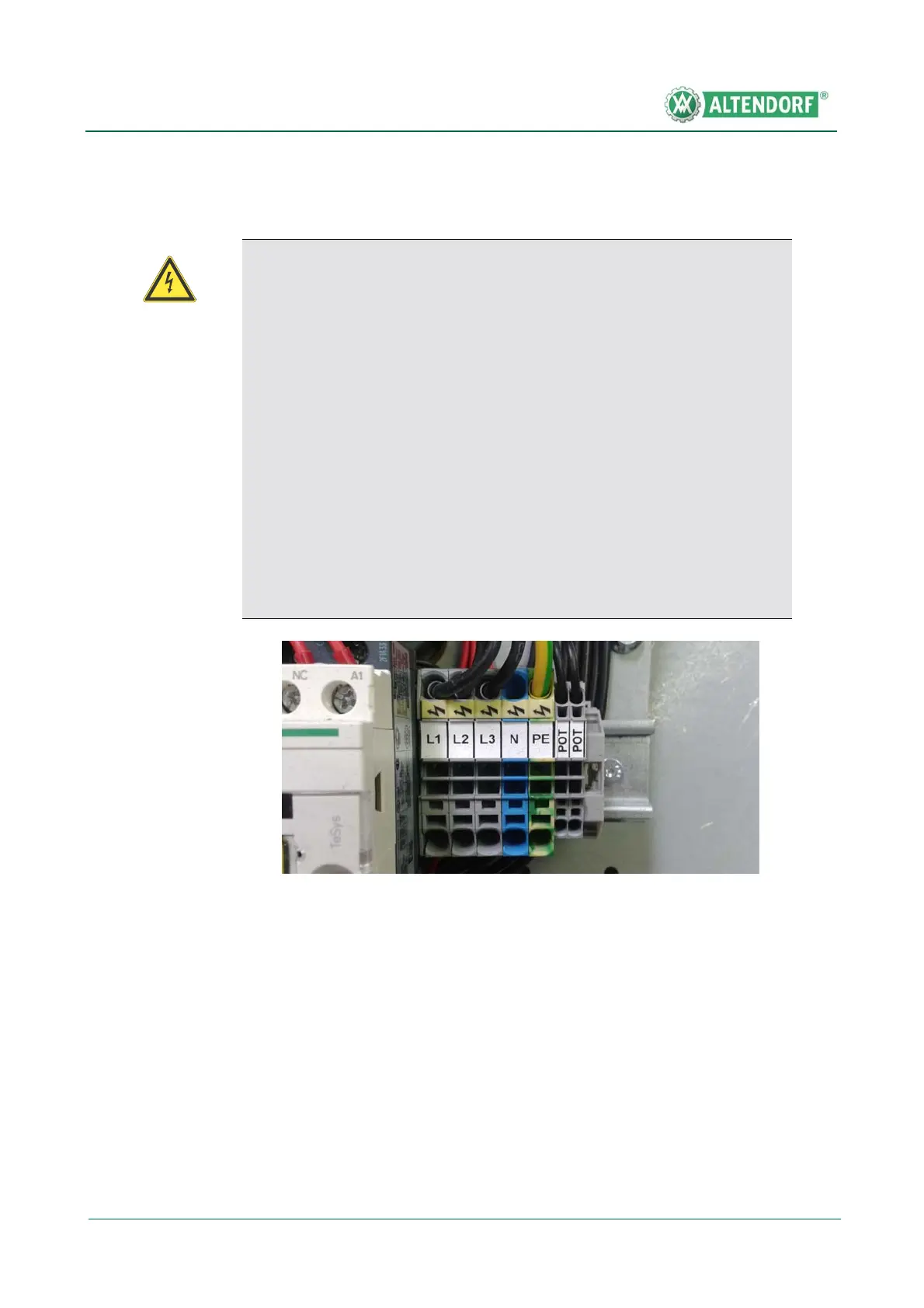
5.3.6 Electrical connection
The mains connection is in the RH switch cabinet on the right-hand side. The
terminals for the supply line are marked L1, L2, L3, N and PE, the terminals for
the potential-free contact for the control of an extraction system are marked
POT. The supply line cross-section and the fuses to be fitted by the user de-
pend on the installed motor rating.
If the machine is connected via a flexible supply line, a rubber-sheathed cable
(wire marking H07RN-F) must be used. Required plug-in device: Round con-
nector in accordance with DIN 49463.
Warning!
Dangerous electric voltage!
All work on the electrical equipment, including connection to the mains
supply, may only be performed by a qualified electrician. Disconnect the
machine from the mains supply before working on the electrical equip-
ment.
• After connecting the supply line, check the rotationaldirection of the
main saw motor by briefly starting up and, if necessary, correct it by
interchanging the two outer conductors in the mains connection box.
Pay attention to the rotational direction arrow on the saw blade cover!
• As far as machines with a VARIO drive are concerned, check the
rotational direction of the scoring saw motor, because the frequency
converter ensures that the directional rotation of the main saw motor
is always correct, regardless of the phase position.
• Only connect or disconnect plug-in connectors when the main switch
has been turned off or disconnected!
Fig. 5-36 Mains connection