4. Configuration
92
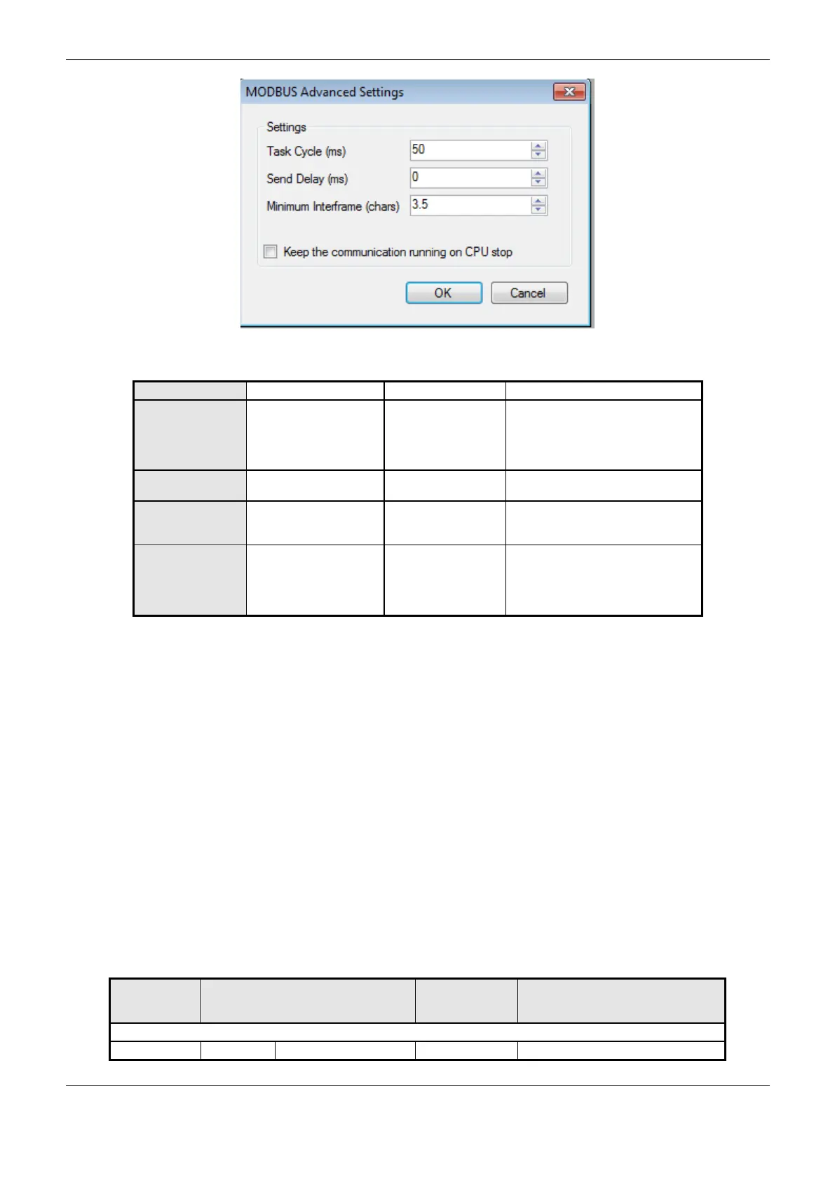
Figure 4-23. Modbus Slave Advanced Configurations
Time for the instance
execution within the
cycle, without
considering its own
execution time
Delay for the
transmission response
Minimum
Interframe (chars)
Minimum silence time
between different
frames
Keep the
communication
running on CPU
stop
Enable the MODBUS
Symbol Slave to run
while the CPU is in
STOP or after a
breakpoint.
Table 4-57. Modbus Slave Advanced Configurations
Notes:
Task Cycle: the user will have to be careful when changing this parameter as it interferes directly in
the answer time, data volume for scan and mainly in the CPU resources balance between
communications and other tasks.
Send Delay: the answer to a MODBUS protocol may cause problems in certain moments, as in the
RS-485 interface or other half-duplex. Sometimes there’s a delay between the slave answer time and
the physical line silence (slave delay to put RTS in zero and put the RS-485 in high impedance state).
To solve this problem, the master can wait the determined time in this field before sending the new
request. On the opposite case, the first bytes transmitted by the master could be lost.
Minimum Interframe: the MODBUS standard defines this time as 3.5 characters, but this parameter
is configurable in order to attend the devices which don’t follow the standard.
The MODBUS Slave protocol diagnostics and commands configured, either by symbolic mapping or
direct representation, are stored in T_DIAG_MODBUS_RTU_SLAVE_1 variables. For the direct
representation mapping, they are also in 4 bytes and 8 words which are described in Table 4-58
(where “n” is the configured value in the %Q Initial Address of Diagnostic Area field).
Direct
Representation
Variable
Diagnostic Variable
T_DIAG_MODBUS_RTU_SLAVE_1 *.
The slave is in execution mode
 Loading...